Analog Discovery Pro (ADP2230) Reference Manual
The Analog Discovery Pro (ADP2230)™ is a mixed signal oscilloscope (MSO) designed for professional engineers. It features analog inputs, analog output, and digital I/O, all operating at up to 125 MS/s. Users can both receive and generate digital signals to test and analyze data from various devices while simultaneously powering those systems with its robust power supply. The feature-packed design allows the ADP2230 to perform the functions of several test and measurement devices and can replace a stack of traditional instruments.
With the free WaveForms software, users can view and capture complex data, perform spectral and network analysis, and quickly retrieve large amounts of data. WaveForms leverages the ADP2230’s deep buffer memory, allowing hundreds of millions of samples to be stored and streamed back to the host computer. WaveForms’ friendly user interface has the feel of traditional benchtop oscilloscopes.


Oscilloscope
Highlighted Features
- Two single-ended BNC analog input channels with 14-bit resolution with up to ±25 V input range
- 50+ MHz bandwidth, up to 125 MS/s per channel
- Up to 128 MS buffer memory per channel
- User-configurable input filters and lock-in amplifier
- FFT, Spectrogram, Eye Diagram, XY Plot views, and more
- Rectangular, Triangular, Hamming, Hann, Cosine, Flat-top, Blackman, Blackman-Harris, Kaiser, and more windowing functions
- Advanced triggering: edge, pulse, transition, hysteresis, hold off, and many others
- Cross-triggering with Logic Analyzer, Waveform Generator, Pattern Generator, or external triggers
- Digital loopback of analog output channels
- Multiple math channels with complex functions
- Cursors with advanced data measurements
- Captured data files can be exported in standard formats
- Scope configurations can be saved, exported, and imported
The Analog Discovery Pro (ADP2230) can be used with WaveForms' Scope instrument to capture analog input data via the analog input channels through BNC connectors. When this instrument is used, the ADP2230's analog input channels act as a two-channel oscilloscope with 14-bit resolution at up to 125 MS/s.
Because the samples themselves are stored in a 16-bit format, when sample rates lower than the Adjustable System Clock Frequency, the additional two bits can be used with averaging (enabled by default) to improve resolution. When sampling at half of the system frequency, data is acquired at an effective 15-bit resolution. When sampling at one quarter or lower of the system frequency, data is acquired at an effective 16-bit resolution.
Analog acquisitions can be triggered by a variety of signal conditions from simple detection of a certain threshold on a rising or falling edge to more advanced triggering for specific slew rates or when a signal leaves a hysteresis defined region. The trigger system can also forward triggers between instruments, allowing cross triggering to occur. For example, an event in the logic analyzer can trigger the oscilloscope. Triggers can be configured to automatically rearm after an acquisition is complete, so that data from multiple acquisitions is streamed into their own memory segments. For more information, see Trigger System and Device Buffering.
Up to 128 MS of analog input data can be captured with the on-board DDR memory. To record more samples than the DDR memory can hold, Record mode can be used to stream data back to the host computer over USB. Users can record both directly to file or use the host computers RAM as a buffer to hold the acquisition until complete. See USB Connectivity and Data Streaming for additional information including USB and sample rate limitations with Record Mode.
- Important Note: Grounding Circuitry
-
The two BNC analog input connectors on the ADP2230 are single-ended and the BNC shielding is connected to the device ground, which is referenced to USB GND. Depending on the PC powering scheme, and other PC connections (Ethernet, audio, etc. – which might also be grounded) the ADP2230 GND reference might be connected to the whole GND system and ultimately to the power network protection (earth ground). The circuit under test might also be connected to earth or possibly floating.
For safety reasons, it is the user’s responsibility to understand the powering and grounding scheme and to make sure that there is a common GND reference between the Analog Discovery Pro (ADP2230) and the circuit under test.
The ADP2230 has a separate small noise buffer that stores minimum and maximum sample values collected during data acquisition and represented on screen as a semi-transparent band in the background of the plot in order to indicate glitches or higher frequency components while running at a lower sample rate than the system frequency. The noise acquisition can be disabled for a faster acquisition rate.
In addition to the two physical analog input channels, the ADP2230 supports digital loopback within the device of the data sent to the Wavegen and Power Supplies to display the configured outputs as traces on the on the Scope plot view. This allows idealized reference signals of the outputs to be easily viewed and used for in-app calculations and filters.

Hardware and software filters are available with in the Scope instrument as additional channels to be shown on the viewing plot. A hardware FIR or IIR filter with different windowing functions and frequency cutoffs are available for each of the two analog inputs on the ADP2230 as additional channels. Each hardware filter can be configured to use the averaged, decimated, or raw ADC data from its associated oscilloscope input.
Software channels, which are calculated by the WaveForms software on the host computer, can also be added as visible channels to the viewing plot. These software channels and filters include straightforward arithmetic operations such as calculating the total amount of power consumed by a system, Butterworth and Chebyshev IIR filters for signal processing, Lock-in amplifiers to extract a signal from surrounding noise, and scriptable math functions. Each software channel can use any of the existing hardware or software channels as the source for their inputs.

|

|
Digital signals from the Logic Analyzer can be simultaneously shown in the Scope instrument with the two types of signals sharing the same time scale for easy comparison. A Scope to Digital option is also available, allowing users to convert their received analog input data into known data protocols. Configurable threshold voltages can be individually selected for each channel. When using the Scope to Digital feature, trigger settings are shared between the analog and digital data shown within the Scope instrument. Because the analog to digital conversion is processed within WaveForms software, patterns in the converted data cannot be used to trigger acquisitions.

Since the ADP2230's analog input channels are shared between instruments, the Oscilloscope instrument cannot be used at the same time as other instruments including the Voltmeter, Data Logger, Spectrum Analyzer, Network Analyzer, Impedance Analyzer, or Tracer instruments.
For more information on the analog input channels, please visit the Analog Discovery Pro (ADP2230) Specifications. For a walkthrough of the different features of WaveForms' Scope instrument, please visit the Using the Oscilloscope guide. Information on the Adjustable System Clock Frequency, the Trigger System, Device Buffering, and USB Connectivity and Data Streaming can be found in their respective sections within this document.
Waveform Generator
Highlighted Features
- One BNC channel with 14-bit resolution, ±5 V output range
- 15 MHz bandwidth, up to 125 MS/s per channel
- Standard waveforms: sine, triangle, sawtooth, noise, ramp up, ramp down, DC voltage, and more
- Advanced waveforms: Sweep, Modulation and summing (phase, AM, FM), custom math, and play mode
- Digital loopback of raw, averaged, or filtered analog input data as waveform outputs
- User-defined arbitrary waveforms: defined within WaveForms software user interface or using standard tools (e.g. Excel)
- Optional standard waveforms control over the two programmable supplies
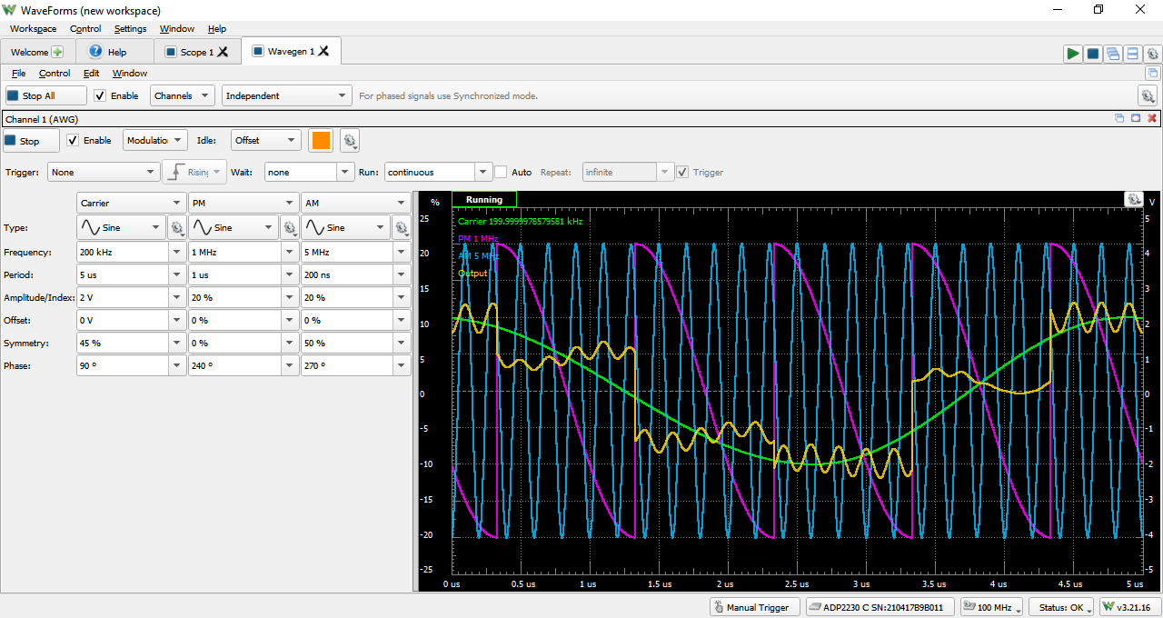
The Analog Discovery Pro (ADP2230) can be used with WaveForms' Wavegen instrument to output analog voltage waves through the BNC connector. When the Wavegen is used, the ADP2230's analog output channel acts as an arbitrary waveform generator with 14-bit resolution at up to 125 MS/s.
Additional separate buffers are allocated towards modulation for frequency or phase modulation (FM/PM) or amplitude and summation (AM/SUM) for complex signals to be generated on the analog output channel. The size of the sample buffers for both the primary AWG channels and the modulation parameters can be set through the Device Configuration.
A 50 Ω output impedance on the analog output channel mitigates any ringing and overshoot that is present on signals with abrupt edges that are being driven in highly capacitive loads. It is recommended to use BNC to minigrabber cables instead of BNC Probes for the analog output to avoid any bandwidth limitations on 1x mode or corresponding signal attenuation on 10x mode.
In addition to controlling the single ended output as a standard or advanced type of waveform, the Analog Discovery Pro (ADP2230) features digital loopback paths within the device that allow the analog output channels to directly use raw, averaged, or filtered analog input data from the Scope instrument. Both programmable power supplies can also be separately controlled as slow, 2.5 Hz or less, standard waveform generators, but with much higher output current capability, providing as much as 3 W per channel.
Since the ADP2230's analog output channel is shared, the Wavegen instrument cannot be used at the same time as the Network Analyzer or Impedance Analyzer instruments. If the analog output or the programmable power supplies are being controlled directly from the Scope instrument or the Supplies instrument, the associated channels cannot be simultaneously controlled through the Wavegen instrument.
For more information on the analog output channels, please visit the Analog Discovery Pro (ADP2230) Specifications. For a walkthrough of the different features of WaveForms' Wavegen instrument, please visit the Using the Waveform Generator guide. Information on the Adjustable System Clock Frequency and the Trigger System can be found in their respective sections within this document.
Power Supplies

Highlighted Features
- Two programmable power supplies (0.5 V to 5 V , -0.5 V to -5 V)
- Up to 1 A or 3 W per channel
- Optional tracking between the two programmable power supplies
- Integrated readback of system temperature, individual voltage rail outputs, and total amount of current used by the system and analog circuitry
- Configurable power limitations to prevent system damage
The Analog Discovery Pro (ADP2230) has two variable power supply rails that can be used to power external circuits under test. These rails can be set to voltage levels between 0.5 V to 5 V and -0.5 V to -5 V respectively, through the use of WaveForms' Supplies instrument. Direct integrated readback of the supplied host voltage and current, power supply voltage outputs, and system temperature is also present in this instrument. Both channels can also be controlled as slow Waveform Generator channels.
The maximum available output current and power depend on how the ADP2230 is powered with the ADP2230 drawing up to 700 mA (~3.5 W) while no instruments are running. When using a 5 VDC auxiliary power supply or a compatible USB port capable of supplying 3 A or higher, each programmable power supply rail can provide up to 1 A, with a wattage limit of 3 W per channel to prevent the internal components of the power supplies from overheating. The point at which the device becomes at risk for overheating is at 11 W or higher. This is noted with a small warning icon in the Hardware Power Limit setting within the Supplies instrument.
Users can set their own preferred device temperature limit and power limit for the ADP2230 to further restrict the recommended conditions. The Hardware Power Limit setting configures the total amount of power provided to the hardware circuitry behind the user supplies; the amount of power able to be sourced from the two supplies will be less than this setting and is dependent on the voltage requested by the user, the load, and the duty cycle of the internal hardware needed to maintain the requested voltage output, among other factors. The Auto option dropdown for the Hardware Power Limit settings has WaveForms automatically set the allowed power based on the USB capabilities or the presence of an auxiliary power supply.

If an overcurrent condition is reached, the power supplies will be stopped and a notification pop-up will appear.

Additional information on the amount of power the ADP2230 requires for different device configurations can be found in Device Configuration. For more information on the programmable power supplies, please visit the Analog Discovery Pro (ADP2230) Specifications. For a walkthrough of the different features of WaveForms' Power Supplies instrument, please visit the Using the Power Supplies guide.
Voltmeter

Highlighted Features
- DC, AC RMS, and True RMS measurements
The Analog Discovery Pro (ADP2230)'s analog inputs can be used with WaveForms' Voltmeter instrument to act as a simple voltmeter. DC voltages, AC RMS voltages, and True RMS voltages can be viewed for each of the two Scope channels.
Since the ADP2230's analog input channels are shared, the Voltmeter instrument cannot be used at the same time as the Oscilloscope, Data Logger, Spectrum Analyzer, Network Analyzer, or Impedance Analyzer instruments.
For more information on the analog input (“Scope”) channels, please visit the Analog Discovery Pro (ADP2230) Specifications. For a walkthrough of the different features of WaveForms' Voltmeter instrument, please visit the Using the Voltmeter guide.
Data Logger

Highlighted Features
- DC, AC RMS, and True RMS measurements
- Capable of logging continuously for 60 days (one sample per minute)
- Scriptable custom measurements
The Analog Discovery Pro (ADP2230) can be used with WaveForms' Logger instrument in order to capture analog input data for a long period of time.
The Data Logger can capture buffers of data at update rates of up to 10 samples per second. The maximum duration of a log is dependent on the update rate, but at the extreme, can run for over a thousand hours. Additional logging configurations and options are available via the Record mode of the Scope instrument.
Since the ADP's analog input channels are shared, the Data Logger instrument cannot be used at the same time as the Oscilloscope, Voltmeter, Spectrum Analyzer, Network Analyzer, or Impedance Analyzer instruments.
For more information on the analog input channels, please visit the Analog Discovery Pro (ADP2230) Specifications. For a walkthrough of the different features of WaveForms' Logger instrument, please visit the Using the Data Logger guide.
Logic Analyzer
Highlighted Features
- 128 MS buffer memory per channel
- Interpreters for SPI, I2C, UART, CAN, I2S, 1-Wire, PS/2, HDMI CEC, Manchester codes, JTAG, GPIB, SWD, and more
- Scripted custom protocols
- Advanced trigger options including pin change, glitch, pulse timeout or length, protocol pattern, and many others
- Cross-triggering between Analog input channels, Logic Analyzer, Pattern Generator, or external trigger
- Adjustable drive strength, slew rate, and pull resistor for all digital channels
- Data file import/export using standard formats
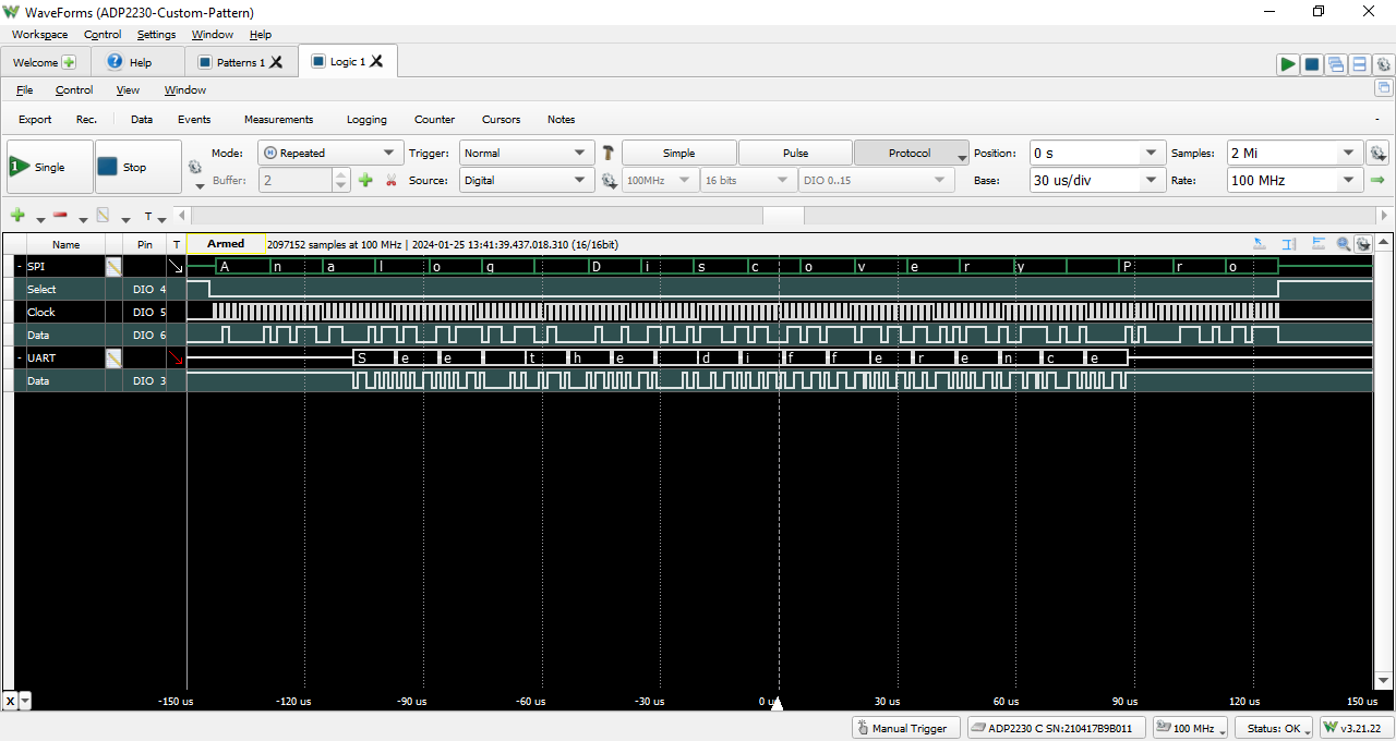
The Analog Discovery Pro (ADP2230) can be used with WaveForms' Logic instrument to act as a Logic Analyzer. When used this way, the 16 digital input/output channels are configured to capture high/low logic states on connected pins and are capable of interfacing with 3.3 V CMOS logic signals and are tolerant to voltages of up to 5 V.
Individual input/output channels can be grouped as buses and protocols. Protocol groups can be used to view the decoded contents of packets of many common communications protocols, including SPI, I2C, UART, CAN, and I2S. Signal states, decoded bus values, and decoded protocols can be used to trigger a Logic Analyzer capture. Protocol triggers include protocol-specific events, like start of transmission, end of transmission, or packet contents matching a value. The trigger system can also forward triggers between instruments, allowing cross triggering to occur. For example, a specific event detected by the oscilloscope can trigger the logic analyzer. Triggers can be configured to automatically rearm after an acquisition is complete, so that data from multiple acquisitions is streamed into their own memory segments. For more information, see Trigger System and Device Buffering.
Up to 128 MS of digital input data can be captured with the on-board DDR memory. To record more samples than the DDR memory can hold, Record mode can be used to stream data back to the host computer over USB. Users can record both directly to file or use the host computers RAM as a buffer to hold the acquisition until complete. See USB Connectivity and Data Streaming for additional information including USB and sample rate limitations with Record Mode.
Sync mode is also available in the Logic Analyzer, allowing users to specify the enable and any associated clock signal edges of their incoming data stream for externally synchronized data capture.
Digital input/output channels used by the Logic Analyzer instrument can still be used by other instruments using the same digital input/output channels but cannot have individual channels driven by two separate instruments. Additionally, the drive strength, slew rate, and internal pull resistors can be changed in the Digital I/O Settings.
For more information on the digital input/output channels, please visit the Analog Discovery Pro (ADP2230) Specifications. For a walkthrough of the different features of WaveForms' Logic Analyzer instrument, please visit the Using the Logic Analyzer guide. Information on the Adjustable System Clock Frequency, the Trigger System, and USB Connectivity and Data Streaming can be found in their respective sections within this document.
Pattern Generator
Highlighted Features
- Multiple preset patterns including Clock, Pulse, Binary Counter, Gray Counter, Johnson Counter, Walking 0/1, Noise, and more
- Custom user defined patterns and truth table ROM logic supported
- Cross-triggering between Analog input channels, Logic Analyzer, Pattern Generator, or external trigger
- Adjustable drive strength, slew rate, and pull resistor for all digital channels
- Data file import and export using standard formats
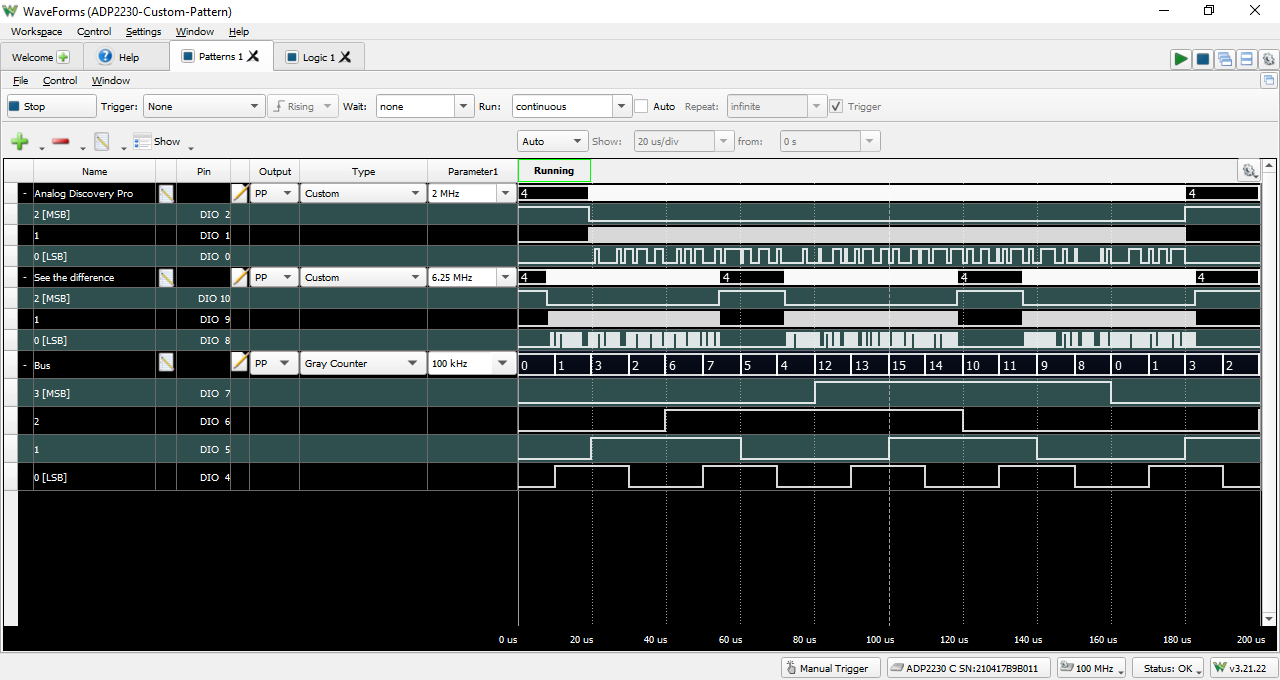
The Analog Discovery Pro (ADP2230) can be used with WaveForms' Patterns instrument to generate logic signal sequences on the 3.3 V CMOS digital input/output pins at sample rate of up to 125 MS/s. Each individual pin or user defined groups of pins can be configured to be push/pull, open drain, open source, or tri-state logic.
Preset patterns such as a clock pulse or a Gray counter can selected as the desired pattern type, along with user defined custom patterns for more unique systems. Simple state machines can be created through the ROM logic option for groups of digital pins.
Individual digital input/output channels used by the Pattern Generator instrument can still be used by other instruments, however, other instruments can only use these shared channels as inputs. Additionally, the drive strength, slew rate, internal pull resistors can be changed in the Digital I/O Settings.
For more information on the digital input/output channels, please visit the Analog Discovery Pro (ADP2230) Specifications. For a walkthrough of the different features of WaveForms' Pattern Generator instrument, please visit the Using the Pattern Generator guide. Information on the Adjustable System Clock Frequency and the Trigger System can be found in their respective sections within this document.
Static I/O
Highlighted Features
- Virtual I/O devices (LEDs, buttons, switches, and displays)
- Easy control over DIO electrical characteristics
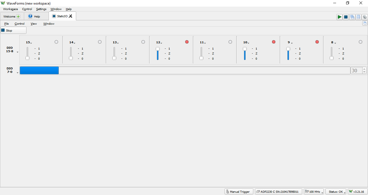
The Analog Discovery Pro (ADP2230) can be used with WaveForms' Static I/O instrument to emulate a variety of user input/output devices on the digital input/output pins. Virtual LEDs, buttons, switches, sliders, and displays can be assigned to specific digital I/O pins, and interacted with within the WaveForms user interface.
The ADP's digital input/output channels use 3.3 V CMOS logic standard for input and output, and are tolerant to input signals up to 5 V. The drive strength, internal pull resistors, and slew can be changed directly changed in this instrument. Additional information about this can be found in the Digital I/O Settings section.
Digital input/output channels used by the Static I/O instrument can still be used by other instruments using the same digital input/output channels, however, other instruments can only use these shared channels as inputs.
For more information on the digital input/output channels, please visit the Analog Discovery Pro (ADP2230) Specifications. For a walkthrough of the different features of WaveForms' Static I/O instrument, please visit the Using the Static I/O guide.
Spectrum Analyzer
Highlighted Features
- FFT and CZT power spectrum algorithms
- Adjustable frequency range modes: center/span, start/stop
- Linear or logarithmic scaling
- Multiple vertical axis options: voltage-peak, voltage-RMS, dBV, dBu, dBVS, and more
- Rectangular, Triangular, Hamming, Hann, Cosine, Flat-top, Blackman-Harris, Kaiser and more windowing functions
- Sample, Peak Hold, Minimum Hold Continuous, Linear RMS Average, and more viewing options for each trace
- Data file import/export using standard formats
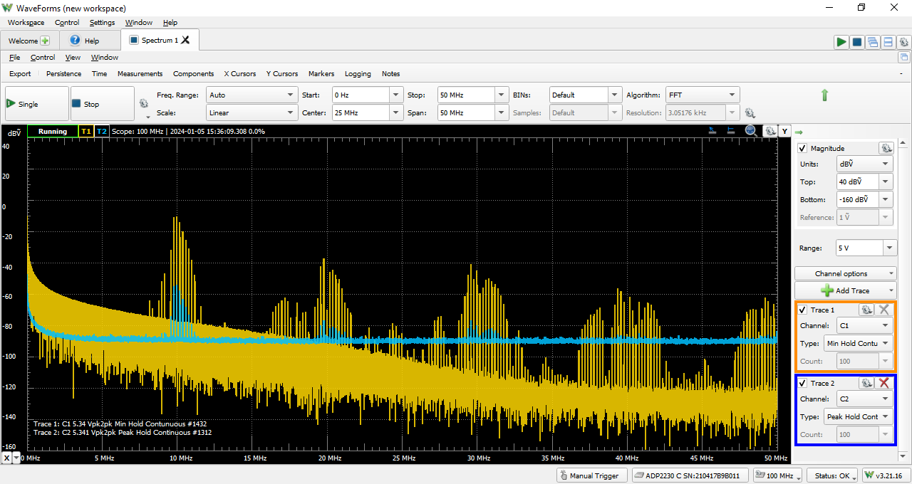
The Analog Discovery Pro (ADP2230) can be used with WaveForms' Spectrum instrument to view the power of frequency-domain components of analog signals captured on the analog input channels. A Fast Fourier Transform or chirp Z-transform (Bluestein's algorithm) can be used as the discrete Fourier transform of choice.
The maximum number of samples and correspondingly number of frequency bins is dependent on the buffer size of the Scope selected in the WaveForms Device Manager and the chosen algorithm. The Spectrum instrument can have a maximum frequency of half of the Adjustable System Clock Frequency.
Device Buffering is available for the Spectrum Analyzer instrument. When enabled, Device Buffering ensures a smoother data experience when utilizing consecutive sweeps such as Peak Hold Continuous. A limit buffer may also be specified to stop the Spectrum Analyzer after a defined number of cpatures.
Because the ADP2230's analog input channels are shared, the Spectrum instrument cannot be used at the same time as the Oscilloscope, Voltmeter, Data Logger, Network Analyzer, or Impedance Analyzer instruments.
For more information on the analog input channels, please visit the Analog Discovery Pro (ADP2230) Specifications. For a walkthrough of the different features of WaveForms' Spectrum Analyzer instrument, please visit the Using the Spectrum Analyzer guide.
Network Analyzer

Highlighted Features
- Bode, Nichols, Nyquist, and FFT diagrams
- Settable input gain and offset
- Selectable Wavegen channel or external signal as the frequency source
- Configurable samples, settle time, and averaging options for each frequency step
- Custom traces and calculations available
- Rectangular, Triangular, Hamming, Hann, Cosine, Flat-top, Blackman-Harris, Kaiser, Blackman, and more windowing functions
The Analog Discovery Pro (ADP2230) can be used with WaveForms' Network instrument to view the amplitude and phase response of a circuit under test. Nichols and Nyquist plots can also be viewed with this instrument. The wave used to perform this sweep can be customized and uses the same resources as the Waveform Generator instrument, but can also be configured to use an external signal to provide input to the circuit under test rather than using the analog output channels.
In order to test the response of the circuit a sweep is performed at a range of frequencies from as low as 20 μHz to as high as one quarter of the Adjustable System Clock Frequency. The accurate upper end of the frequency range is dependent on the bandwidth of the frequency signal source, whether generated directly by the ADP2230 or an external system, as well as the bandwidth of the analog inputs of the ADP2230.
Since the ADP2230's analog input and output channels are shared, the Network Analyzer instrument cannot be used at the same time as the Oscilloscope, Waveform Generator, Voltmeter, Data Logger, Spectrum Analyzer, or Impedance Analyzer instruments.
For more information on the analog output and analog input channels, please visit the Analog Discovery Pro (ADP2230) Specifications. For a walkthrough of the different features of WaveForms' Network Analyzer instrument, please visit the Using the Network Analyzer guide.
Impedance Analyzer
Highlighted Features
- Plot views for Input Gain, Voltage, Current, Impedance, Admittance, Inductance, Capacitance, Nyquist, Custom, and more
- Alternative simple Meter view
- Selectable external compensation circuit topographies
- Data file export using standard formats
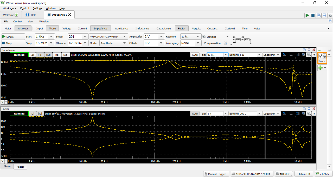
The Analog Discovery Pro (ADP2230) can be used with WaveForms' Impedance instrument to view a wide variety of frequency response characteristics of a device under test. Predefined and custom plots can be used to present the results of a wide variety of different mathematical operations on buffered data.
A sweep from the ADP2230 analog outputs is performed in order to test the response of of a DUT within an external reference circuit at a range of frequencies from 20 μHz to one quarter of the Adjustable System Clock Frequency. Different topologies of the external reference circuit can be selected from a variety of presets, with configurable amplitude and offset.

|

|
Since the ADP2230's analog input and output channels are shared, the Impedance Analyzer instrument cannot be used at the same time as the Oscilloscope, Waveform Generator, Voltmeter, Data Logger, Spectrum Analyzer, or Network Analyzer instruments.
For more information on the analog output and analog input channels, please visit the Analog Discovery Pro (ADP2230) Specifications. For a walkthrough of the different features of WaveForms' Impedance Analyzer instrument, please visit the Using the Impedance Analyzer guide.
Protocol Analyzer

Highlighted Features
- Supports UART, SPI, I2C, CAN, HDMI CEC, JTAG, SWD, and AVR programming protocols
- Generate UART, SPI, I2C, CAN, HDMI CEC, and AVR programming sequences
- Scriptable transaction sequences for SPI, I2C, and SWD
- Configurable data rates, modes, polarity, and more
- Save logged transactions to data files
The Analog Discovery Pro (ADP2230) can be used with WaveForms' Protocol instrument to work with common communication protocols. The ADP2230 can transmit or receive data in UART, SPI, I2C, CAN, CEC, SWD, and AVR transactions. It can spy on transactions between other devices using any supported protocol within the Protocol instrument. Any of the digital input/output channels can be used. Custom scripts can be written within the Protocol Analyzer instrument to generate sequences of SPI, I2C, or SWD transactions. The Logic instrument can optionally be used to directly receive and debug incoming digital data.
As only a single protocol engine is implemented in hardware, the Protocol instrument can only be used to control a single protocol at a time. The Scripts instrument can be used to support multiple protocols in one test by changing the mode of the protocol engine partway through - effectively closing one protocol tab and opening another. Alternatively, the Patterns instrument can be used to simulate a custom pattern that simulates a predetermined protocol output.
Because the Protocol instrument uses the same hardware resources as the Logic Analyzer and Pattern Generator instruments, the Protocol Analyzer cannot be used at the same time as these instruments.
The ADP2230's digital input/output channels use 3.3 V CMOS logic standard for input and output, and are tolerant to input signals up to 5 V. The drive strength, internal pull resistors, and slew can be changed directly changed in this instrument. Additional information about this can be found in the Digital I/O settings section.
For more information on the digital input/output channels, please visit the Analog Discovery Pro (ADP2230) Specifications. For a walkthrough of the different features of WaveForms' Protocol Analyzer instrument, please visit the Using the Protocol Analyzer guide.
WaveForms Script Editor

Highlighted Features
- Available directly within the WaveForms application
- Simultaneous control of all instruments through JavaScript
- Automatable GUI actions
- Custom data analysis and manipulation functions
Each of WaveForms' instruments can be controlled through scripts within the WaveForms application itself. The Script instrument allows the user to write and run JavaScript code (based on the EMCAScript and ECMA-262 specification) that can control the rest of the WaveForms application through an extensive API, allowing the user to configure and run many instruments at the same time, in an easily repeatable way. Hovering over different scriptable actions with in the GUI shows the corresponding Script function in the lower left hand corner of WaveForms.
The Script instrument is intended to enable users to automate some features available within different instruments, such as changing a PWM frequency over a preset number of runs. Other features such as setting up channels, naming individual traces, and static configuration are far easier to configure from within that particular instruments GUI rather than from the Script instrument. As each WaveForms workspace saves both the Script and individual instrument settings, users can define different configurations of an instrument from within its own GUI and the Script tool without needing to manually define and setup everything a single location.
For a walkthrough of the different features of WaveForms' Script instrument, please visit the Using Scripts guide.
Additional Features
First Party Software Support
WaveForms
WaveForms is Digilent's free Test and Measurement software application compatible with all of Digilent's Discovery family devices. With support for Mac, Linux, and Windows operating systems, users can easily configure and control all of the virtual instruments offered by the Analog Discovery Pro (ADP2230).
More information about WaveForms including a getting started guide and examples can be found in the WaveForms Resource Center.
WaveForms Software Development Kit (SDK)
WaveForms SDK is a set of software libraries and examples included with WaveForms that can be used to develop custom applications that can control Digilent Test and Measurement devices outside of the WaveForms application. With support for a variety of languages including C/C++, C#, MATLAB, Python, and Visual Basic, users can easily control hardware channels and virtual instruments of multiple devices without ever needing to open WaveForms itself.
More information about WaveForms SDK including a getting started guide and examples can be found in the WaveForms SDK Resource Center.
Third Party Software Support
Digilent has created packages for both MATLAB and LabVIEW to provide users with flexibility in the environment used for both data acquisition and subsequent analysis. Each offering provides a curated experience to let users who are more comfortable in different development environments still have access to all of the power contained within the Analog Discovery Pro (ADP2230). Further customization and control of the ADP2230 can be done through Digilent's WaveForms SDK, letting users create their own applications in C/C++, C#, Python, and Visual Basic.
A guide for using WaveForms with LabVIEW can be found in Digilent's Getting Started with LabVIEW guide and a similar guide for MATLAB can be found in Digilent's Getting Started with MATLAB guide.
Adjustable System Clock Frequency
Each of the primary systems of the ADP2230 — the analog inputs, analog outputs, and digital I/O pins — have their sample rate controlled by an adjustable system clock from rates ranging between 50 MHz up to 125 MHz with a default rate of 100 MHz. Users can change the system frequency through the WaveForms Device options; if a manually selected frequency is not achievable, the actual frequency achieved by the FPGA will be listed.
External Clocking
The ADP2230, and correspondingly the Adjustable System Clock Frequency, can also be used with an external reference clock ranging between 10 MHz and 50 MHz applied to Trigger 1 (T1). The FPGA directly forwards the reference clock from T1 to the dedicated PLL instead of using the 25 MHz oscillator. With a 10 MHz external reference clock, less than 4 ps of jitter was observed on the ADC clock relative to the local oscillator.

By default, when the Analog Discovery Pro (ADP2230) is used as a standalone device or is producing an external clock, a local oscillator provides a clock signal to a dedicated low-jitter PLL to drive the ADC and DAC clocks. A PLL within the FPGA is used to generate internal clocks as well as a low frequency clock ranging between 10 MHz and 50 MHz that can be optionally output on the two Trigger I/O pins.

Additional information about the trigger pin can be found in the Trigger System and the Analog Discovery Pro (ADP2230) Specifications.
Trigger System
Each primary system of the ADP2230 — the analog inputs, analog outputs, and digital I/O pins, controlled by the Scope, Wavegen, Logic and Patterns instruments respectively — has its own trigger logic, which has access to the two physical trigger pins and the central trigger bus. Each of the instruments can be triggered by trigger conditions it generates itself, or by any other instrument. For example, a Logic Analyzer acquisition could be triggered to on the known starting value of an error code. The start of the Logic acquisition could then be routed through the trigger bus to the Scope instrument and cause it to be collecting analog data to observe how the external system is reacting to the error code.
The two physical trigger pins by default are set to receive an external signal. They can also output a trigger from generated any instrument on the trigger bus. The trigger pins can also uniformly have their slew, drive, and pull type set by the Digital I/O Settings.
The trigger type can be set to “Auto” (the default setting) where if the trigger condition is not detected within a maximum two seconds (minimum of holdoff plus specified time span) the acquisition will start automatically, “Normal” where the system waits to start the acquisition until the condition is met, and “None” where the acquisition starts immediately.

Each of these active systems will step through different states while acquiring or generating a signal. If multiple instances or instruments of the same type are opened, the last used instance (determined by pressing Run or Stop for an individual instrument) will control the state that the Analog Discovery Pro (ADP2230) is in. Other instruments sharing the same hardware resources will display a Busy status.
Different states of the systems include:
- Ready - The instrument is not running and ready to be configured
- Config - The instrument is being configured and the acquisition buffer is prefilled with data
- Armed - The instrument is armed and waiting for the user specified trigger event to occur. The acquisition buffer is prefilled with data
- Trig'd - The acquisition is triggered based on a predefined condition in the trigger system
- Auto - The trigger condition timed out and the acquisition started automatically
- Wait - The instrument waits a predefined amount of time before starting its process (known as Holdoff for the Oscilloscope and Logic Analyzer)
- Done - The acquisition was completed
- Stop - The instrument was stopped and is effectively reset to the ready state
- Scan - The instrument is running in scan screen or shift mode
- Error - Something went wrong, such as if the device was disconnected from the host computer
Systems that generate a signal, such as the Waveform Generator and Pattern Generator, have options implement wait time, run time, and repeat parameters to easily generate short, precise sequences known as burst signals.
Figure 12 shows a state diagram for one of the generator instruments showing the flow of the system starting out in Ready, becoming configured, checking to see if the user has requested to start the generation, then arming system with the desired trigger, waiting the specified amount of time before starting the signal generation, generating the signal for the requested amount of time (staying in the Run state if the continuous option was specified), then checking to see if the requested number of signal repetitions has been completed. If more repetitions remain or the infinite repetition option was set, the system then either goes back to the Armed state to await for another trigger or to the Wait state if a trigger source of 'None' was selected, before eventually proceeding to the Done state. If the user stops the generator before the Done state is reached, the “Stop” state will be indicated and the instrument will be ready to be reconfigured or start again.

Additional information about the Trigger system and the physical trigger electrical characteristics can be found in the Analog Discovery Pro (ADP2230) Specifications.
Device Buffering
The Analog Discovery Pro (ADP2230) supports memory segmentation of its embedded DDR memory between acquisitions. This lets users quickly capture repetitive signals in multiple sections of DDR, such as repeated pulse conditions, without having to wait for the ADP2230 to rearm itself after USB communication with the WaveForms software. The hardware will auto re-arm the trigger within 1 to 2 μS after each acquisition.
Within WaveForms, users will see the option of Buffers, Limit and Buffer Stop, and Device Buffering. Buffers are the number of acquisitions held by the WaveForms software on the host computer and is configurable to hold up to 10 000 acquisitions. The Run setting lets users choose to have the WaveForms software to either continuously acquire data and fill the circular buffer, stop the acquisition when all buffers have been filled, or when a separately defined limit number is reached. The Device Buffering checkbox enables memory segmentation of the DDR memory within the hardware device.

Each acquisition done by the ADP2230 is transferred to the host computer one by one. Depending on the sample rate and the number of samples chosen per acquisition, the transfer and processing of each acquisition can take much more time than each individual acquisition done in hardware. This is much more noticeable when device buffering is used to ensure low latency captures. To limit impact of the discrepancy in total time required between capturing and processing data, it is recommended to use the Buffer or Limit stop to get a set number of low latency captures and then later inspect them individually.
Device Configuration
The Analog Discovery Pro (ADP2230) has multiple device configuration options to allocate different predefined buffer sizes for the analog input, analog output, and digital I/O systems.
The Auto configuration will recommend either configuration #2 or #3, depending on how WaveForms detects that the ADP2230 is being powered. When more than 5 W of power is available to the device configuration #3 with the DDR memory enabled will be selected. Using a USB Type C port capable of at least 1.5 A output or the included 5 V 4 A auxiliary power supply will satisfy this condition.
If a DDR memory configuration is selected when less than 5 W of available power is detected, WaveForms will provide a pop-up to indicate that more power required for the DDR enabled configuration.

A summary of the different configuration options for the ADP2230 to choose from in the WaveForms Device Manager is available in Table 1.
| Configuration Number | Power Requirement | Oscilloscope | Waveform Generator | Logic Analyzer | Pattern Generator |
|---|---|---|---|---|---|
| 1 (Auto, Default) | WaveForms automatically selects configuration #2 or #3, depending on available power | ||||
| 2 (Block RAM Memory Only) | >2.7 W | 32 kS per channel, 2 kS noise buffer for each channel | 16 kS | 16 kS per channel | 16 kS per channel |
| 3 (DDR Memory) | >5 W1) | 64 MS per channel, 1 kS noise buffer for each channel | 32 kS | 128 MS per channel | 32 kS per channel |
| 4 (DDR Memory, Oscilloscope prioritized) | >5 W2) | 128 MS per channel, 1 kS noise buffer for each channel | 32 kS | The Logic and Protocol analyzers are not supported in this configuration. | 32 kS per channel |
Note: Memory sizes, including buffer sizes, specified in units like kS and MS, are rounded from equivalent binary power units, such as MiS. For example, a listed 64 MS is rounded from 64 MiS, which is 67,108,864 samples.
USB Connectivity and Data Streaming
The Analog Discovery Pro (ADP2230) can be powered in two ways; over USB alone or via an auxiliary power supply. A compatible 5 V 4 A power supply is included in the product kit. The USB connection type and the amount of current available to the device is automatically detected by the ADP2230 and displayed in the WaveForms Device Manager.


WaveForms can allow the device to draw additional current from compatible USB ports beyond what is listed in the WaveForms Device Manager up to a maximum of 15 Watts. If the ADP2230 has the hardware power limit set to more than 11 W, a warning appears within the Power Supplies to indicate that there is a risk of overheating the device in high temperature conditions.
The ADP2230 uses a USB Type-C® connector that supports 5 Gb/s transfer speeds and comes with a USB Type-C to Type-C cable which supports this transfer rate. WaveForms will correctly inform the user of the negotiated connection type between the ADP2230 and the host computers operating system within the WaveForms Device Manager, showing “USB3 5Gbps” for a USB 3.2 Gen 1 connection and “USB2 HS 480Mbps” for a USB 2.0 connection.


If you use a different USB Type-C to Type-C cable than the one Digilent provides with the ADP2230 or a USB Standard-A to USB Type-C cable, a 5 Gb/s transfer rate is not guaranteed. This transfer rate can only be achieved if the controller and port on the device, the controller and port on the host, and the cable in between the two systems all support the same rate.
While imprecise, a visual inspection of a cable can be done as an indication of if a cable supports a 5 Gb/s or faster transfer rate thanks to the increased number of data lanes required to support this transfer rate. This increased number of lanes necessitates a thicker cable to properly house all of the wires going through the cable. A selection of visual comparisons between a cable that supports 480 Mb/s vs one that supports 5 Gb/s is provided below.

|

|


|
However, like many transfer speed specifications, the 5 Gb/s is a theoretical maximum transfer rate and not a rate that most users will see in their daily interactions with the ADP2230 or any device that supports a 5 Gb/s transfer rate due to protocol overhead, bus activity, the number of bytes being transferred, and other latency factors.
Digital I/O Settings
The slew rate, drive strength, and pull type for the 18 digital I/O pins on the Analog Discovery Pro (ADP2230), including both the 16 I/O pins shared between the Logic Analyzer and Pattern Generator and the two Trigger I/O pins, can be set by the user within the Device Options setting or the Logic Analyzer Instrument.
Slew can be set to slow (the default value) or fast. Drive can be set to 4 mA, 8 mA (the default value), 12 mA, or 16 mA. The pulltype can be set to none (the default value), pulldown, pullup, or keeper. The selected setting will applied to all of the digital I/O pins on the ADP2230.
Additional information about these settings can be found in Xilinx's 7 Series FPGA SelectIO Resources User Guide, UG471, in the 7 Series FPGA SelectIO Attributes/Constraints section.
Pinout Reference
The Analog Discovery Pro (ADP2230) provides access to its digital and trigger I/Os, a number of ground pins, and programmable power supplies through a 2×16 100 mil spaced header. Users can easily access these pins through the included color-coded MTE cable. The Arbitrary Waveform Generator and two Oscilloscope channels are provided through their own BNC connectors.

LED States
The power LED on the back of the Analog Discovery Pro (ADP2230) has four different states: fully lit to indicate when both the analog and digital rails are active and powered, dimly lit to indicate when the digital rails are powered but the device is not active, blinking at ~4 Hz when there is a fault condition with the power supplies (not pictured), and off when the device is not powered.


