Using the Impedance Analyzer
Introduction
Impedance Analyzers are used to measure a circuit-under-test's response to input signals of differing frequencies. This guide explains the use of WaveForms' Impedance Analyzer instrument. This instrument is also referred to as Impedance within WaveForms.
Prerequisites
- Digilent Test and Measurement Device with Analog Inputs and Outputs:
- Computer with WaveForms Software Installed
- A Reference Circuit, which can be provided by:
- Impedance Analyzer Adapter for Analog Discovery, if using the Analog Discovery 3, Analog Discovery 2, or Analog Discovery (Legacy).
- A reference resistor appropriate for the specific load, as described in Section 2 of this document.
Guide
1. Opening the Impedance Analyzer Instrument
1.1
Plug in the Test & Measurement Device, then start WaveForms and make sure the device is connected.
If no device is connected to the host computer when WaveForms launches, the Device Manager will be launched. Make sure that the device is plugged in and turned on, at which point it will appear in the Device Manager's device list (1). Click on the device in the list to select it, then click the Select button (2) to close the Device Manager.
Note: “DEMO” devices are also listed, which allow the user to use WaveForms and create projects without a physical device.
Note: The Device Manager can be opened by clicking on the “Connected Device” button in the bottom right corner of the screen (3), or by selecting “Device Manager” from the “Settings” menu at the top of the screen.
1.2
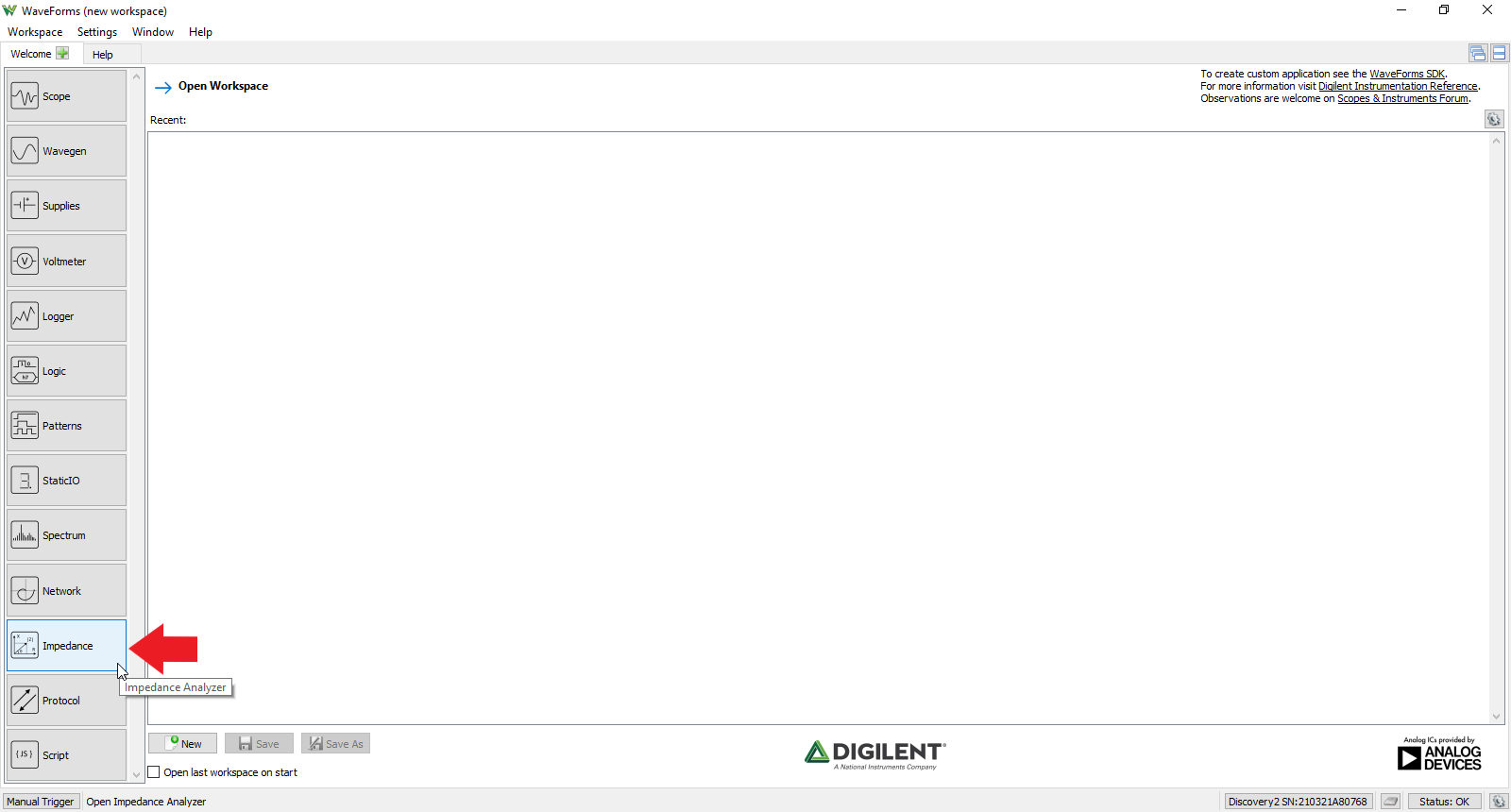
Once the Welcome page loads, in the instrument panel at the left side of the window, click on the “Impedance” button to open the Impedance Analyzer instrument.
1.3
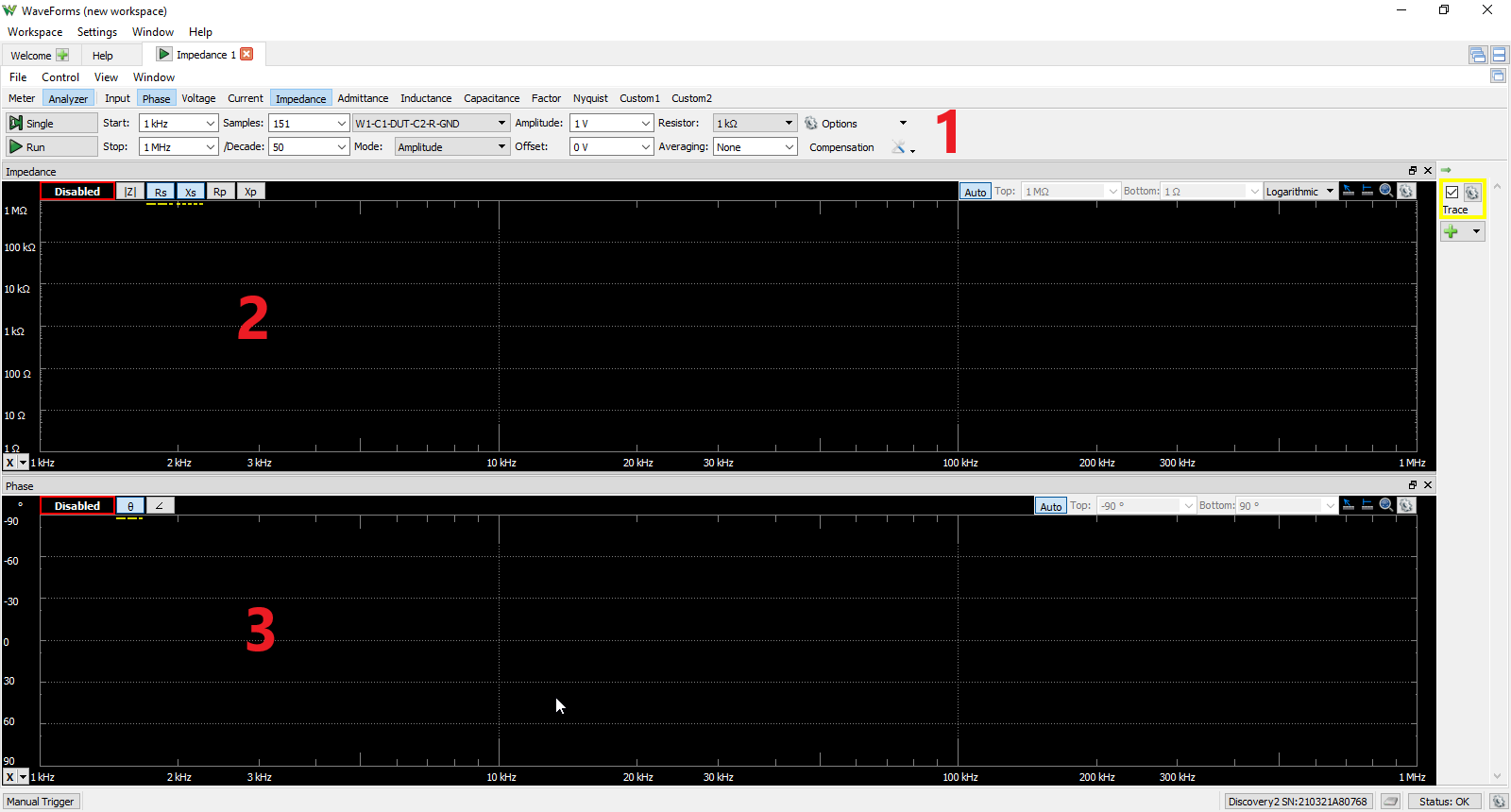
Once the Impedance Analyzer Instrument opens, the window contains the Control Bar (1) at the top with the Impedance plot plane (2) below that and the Phase plot plane (3) at the bottom as seen in the picture to the right.
2. Using the Impedance Analyzer
An Impedance Analyzer is used to analyze capacitive and inductive elements. This section walks through setting up the Impedance Analyzer Instrument to capture the impedance and phase of a common capacitor over a default frequency range. It uses the Waveform Generator and Oscilloscope instruments in addition to an external reference resistor whose value is determined from a table in relation to the range of capacitance or inductance of the device under test (DUT). This table is presented to the right. When the Impedance Analyzer Instrument is started, the Oscilloscope and Waveform Generator are stopped if they were running and their status shows “Busy”. The Impedance Analyzer Instrument takes control over these instruments while running.
2.1 Hardware Setup
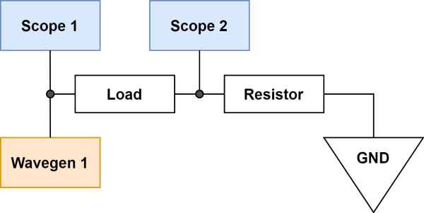
In this tutorial, the impedance of a 10nF capacitor is measured. Referring to the previous table, a 10kOhm reference resistor is required for this value of capacitance. Refer to the “Load First” diagram to the right for how to set up this circuit (the capacitor is the load and the reference resistor is the resistor in the diagram.)
Note: The Analog Input channels can be used with BNC Cables. For more information, see the Using the Oscilloscope guide.
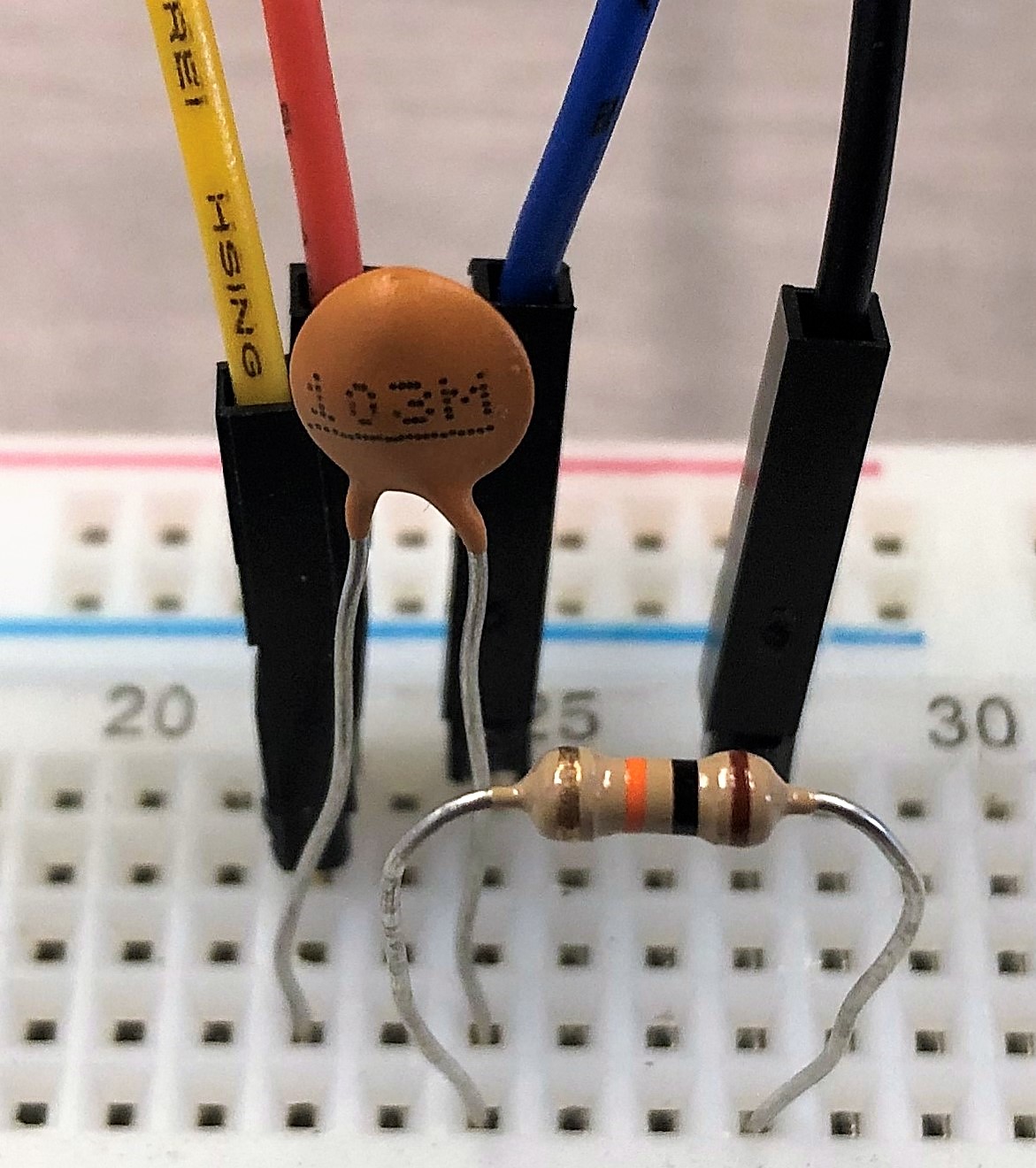
An example of this setup is shown in the picture to the right:
- Capacitor and reference resistor connected in series
- Oscilloscope Channel 1 (solid orange wire) and Waveform Generator Channel 1 (solid yellow wire) connected to the free end of the capacitor
- Oscilloscope Channel 2 (solid blue wire) connected to the node shared by the capacitor and the reference resistor
- Ground (black wire) connected to the free end of the reference resistor
Note: If desired, BNC Cables can be used to connect the Analog I/O channels to the circuit under test. This is discussed in detail in the Using the Oscilloscope guide.
When using a device with BNC cables, make sure to set the attenuation of the oscilloscope probes in the options menu (with the gear icon).
The Impedance Analyzer Adapter for Analog Discovery makes use of the Impedance Analyzer Instrument easier. It automatically selects the best configuration for several reference resistors and relays to create a reference circuit to measure an unknown impedance.
- Click here if using the Impedance Analyzer Adapter for Analog Discovery
-
The Impedance Analyzer Adapter uses a “Load First” topology, which is summarized in the diagram to the right.
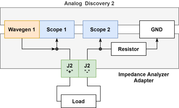
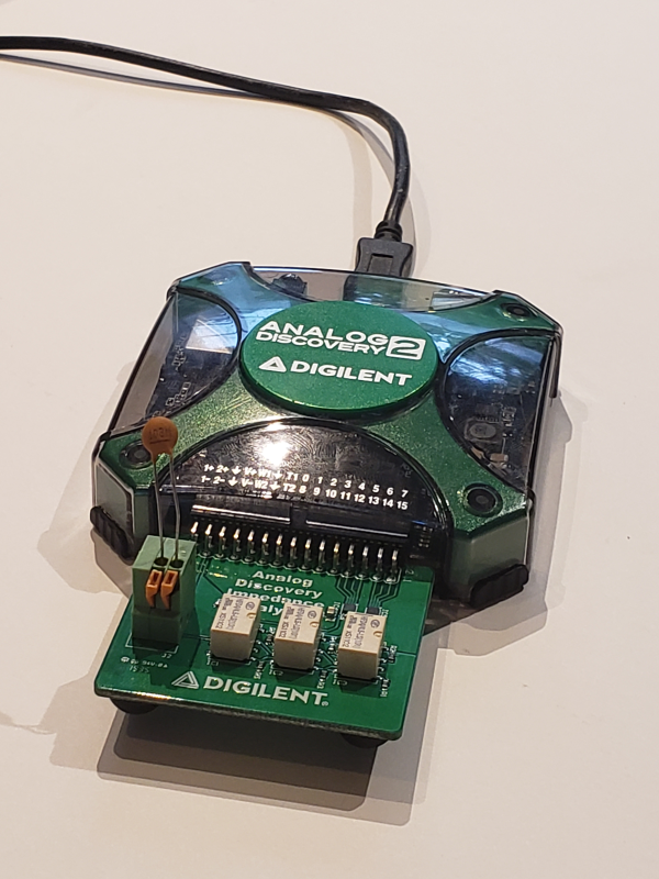
The Impedance Analyzer Adapter attaches to the MTE cable connector slot on the Analog Discovery. A load, whether a single component, or a circuit to test, should be connected to connector J2, and the component or jumpers should be locked in place with the orange clips.
2.2 Software Setup
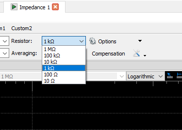
All software parameters will be left as default like in Section 1 with the exception of changing the reference resistor value. On the Control Bar, select the Resistor drop-down menu and click on 10kOhm as shown in the picture to the right.
- Click here if using the Impedance Analyzer Adapter for Analog Discovery
-
Change the Reference Resistor Topology dropdown to “Adapter”, as seen to the right.

2.3 Run Impedance Analyzer Instrument
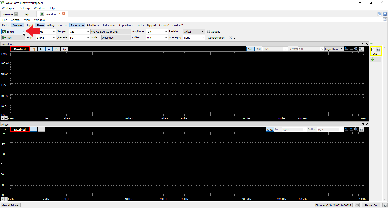
To start collecting data, navigate to the left of the Control Bar and click the “Single” button as shown in the picture to the right.
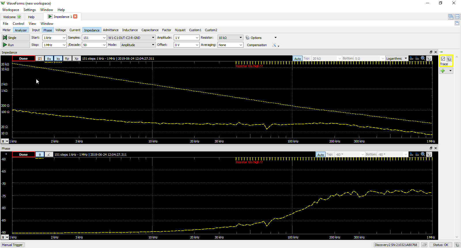
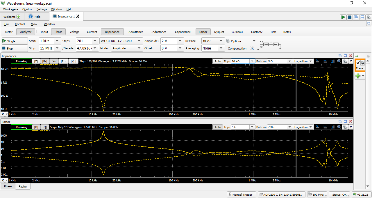
The impedance and phase of the capacitor as a function of frequency is now plotted in the plot plane as shown in the picture to the right.
Note: Using Multiple Instruments
The Impedance Analyzer Instrument can be used with other WaveForms instruments. Using multiple instruments at the same time is helpful in a wide variety of situations. One example would be to use the the Power Supplies to provide power to the Impedance Analyzer Adapters's circuit under test. More information on how instruments can be operated together can be found in the Using Cross Triggering guide.
It should be noted that the Analog Input channels cannot be shared by multiple instruments. When the Impedance Analyzer is enabled, any other instruments using the Analog Input channels are disabled. Other instruments that use the Analog Input channels include the Oscilloscope, Voltmeter, Data Logger, Spectrum Analyzer, and Network Analyzer. The same is true for the Analog Output channels, which are shared by the Waveform Generator and Network Analyzer.
3. Impedance Analyzer Instrument User Interface Overview
This section walks through the various tools and configurations for the Impedance Analyzer Instrument.
3.1 Meter/Analyzer Mode Toggle Bar
The Meter/Analyzer toggle bar is located above the Control Bar and below the File drop-down menu as seen in the picture to the right. Selecting “Meter” will hide all Analyzer plot planes a display a table of measured values associated with the DUT at a given frequency. Selecting “Analyzer” allows the user to generate various plots for the DUT. These modes are discussed in further detail in the subsequent sections, respectively.
3.1.1 Meter Mode
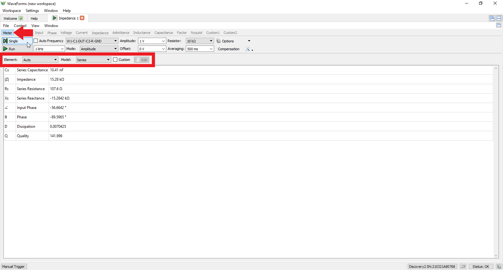
Selecting Meter from the Meter/Analyzer Toggle Bar (as shown with the red arrow in the picture to the right) does the following:
- Hides the plot planes from Analyzer Mode
- Displays a table of values associated with the DUT
- Adds a new toolbar (shown in the red rectangle in the picture to the right)
The new toolbar provides the following features:
- Element: Determine (Auto) or select the type of circuit element the DUT is or models (Inductance, Capacitance, or Resistance)
- Model: Select whether DUT models a Parallel or Series connection
- Custom: Check this box to customize the values in the table
- Edit: Click on this button to open a new window for choosing which measured values are to be displayed in the Meter table
3.1.2 Analyzer Mode
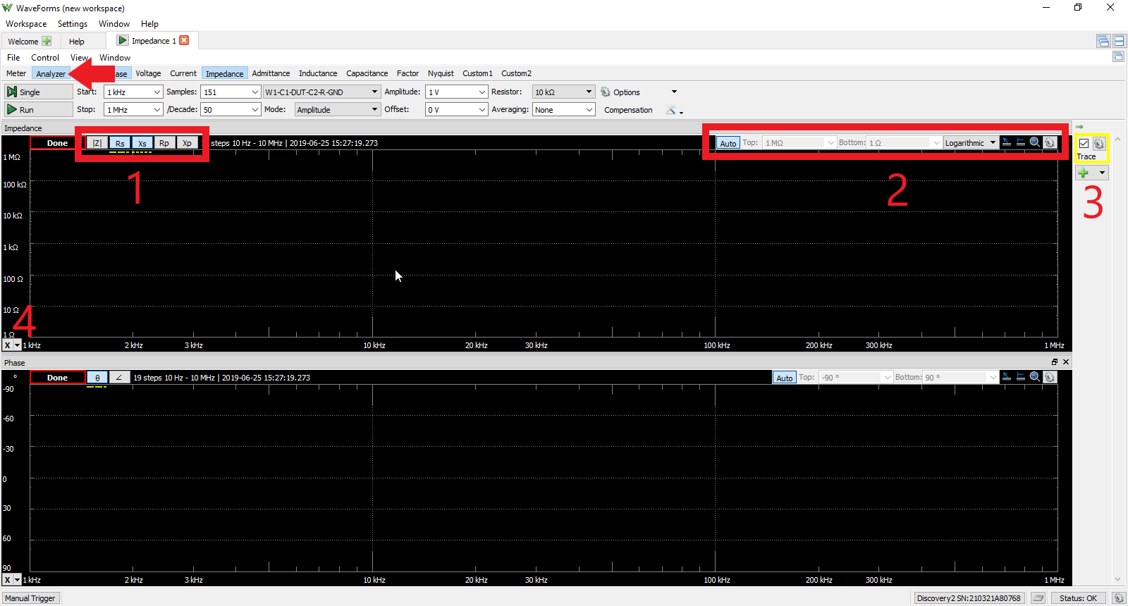
Selecting Analyzer from the Meter/Analyzer Toggle Bar (as shown with the red arrow in the picture to the right) provides the user with an array of plots that can be generated with each acquisition and is the Impedance Analyzer's default mode. Each plot has its own selection of parameters that can be displayed or removed from the plot plane and are found in the upper left corner of each plot (1). Each plot also has additional manual range and scale options found in the top right corner (2). Additional traces may be added from the traces menu (3) located to the right of the plot plane, and data cursors (4) can be generated by clicking the X in the bottom left corner of a plot. The plots available to the user and the parameters that can be displayed on that plot are listed below:
- Input: Gain Magnitude
- Phase: Phase, Input Phase
- Voltage: RMS, Real, Imaginary
- Current: RMS, Real, Imaginary
- Impedance: Impedance Magnitude, Series Resistance, Series Reactance, Parallel Resistance, Parallel Reactance
- Admittance: Admittance Magnitude, Parallel Conductance, Parallel Susceptance, Series Conductance, Series Susceptance
- Inductance: Series Inductance, Parallel Inductance
- Capacitance: Series Capacitance, Parallel Capacitance
- Factor: D and Q plots
- Nyquist: Gain and phase of acquisition in angular plot
- Custom1: Custom parameters as programmed by the user
- Custom2: Custom parameters as programmed by the user
3.2 Control Bar
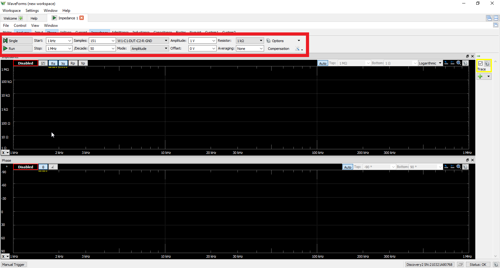
Located above the plot planes is the Control Bar (as shown in Section 1.3) where the Impedance Analyzer Instrument can be further configured. The elements of the Control Bar are explained in the following subsections as they are seen from left to right in the Control Bar.
3.2.1 Acquisition Buttons
The “Single” and “Run” acquisition buttons will perform either a single acquisition or continuous acquisition on the DUT, respectively.
3.2.2 Start/Stop Frequency
The Start and Stop drop-down menus correspond to the start and stop frequency of the acquisition, respectively. These values can be changed by clicking on the drop-down menu arrow, scrolling to the desired frequency, and selecting it or by typing the desired frequency manually into the text field.
3.2.3 Samples and Samples/Decade
The Samples and /Decade drop-down menus correspond to the number of samples per acquisition and the division of those samples per decade on the plot plane, respectively. These values can be changed by clicking on the drop-down menu arrow, scrolling to the desired frequency, and selecting it or by typing the desired value manually into the text field.
Note: Changing one of these fields will update the other accordingly.
3.2.4 DUT and Reference Resistor Topology Arrangement
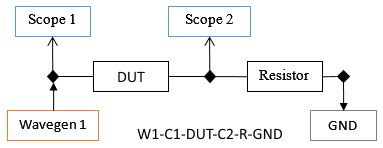
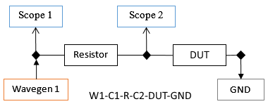
This drop-down menu allow the user to select the appropriate topology for the DUT and reference resistor. There are four choices available, each are described below with reference diagrams to the right.
Note: The “Nodes” that are referenced in the following diagrams are the diamond shape connection points and are numbered such that they are increasing from left to right.
W1-C1-DUT-C2-R-GND: This is used when the DUT is normally loaded at the output.
- Node 1: Wavegen Channel 1, Scope Channel 1+, and the DUT input
- Node 2: Scope Channel 2+, DUT output, and the reference resistor
- Node 3: Reference resistor and ground
W1-C1-R-C2-DUT-GND: This is used when the DUT is normally grounded at the output.
- Node 1: Wavegen Channel 1, Scope Channel 1+, and the reference resistor
- Node 2: Scope Channel 2+, reference resistor, and the DUT input
- Node 3: DUT output and ground
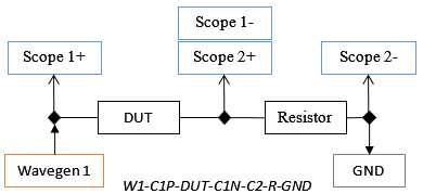
W1-C1P-DUT-C1N-C2-R-GND: This variation of the first topology provides differential measurements across both the DUT and reference resistor. This is used when the DUT is normally loaded at the output.
- Node 1: Wavegen Channel 1, Scope Channel 1+, and the DUT input
- Node 2: Scope Channel 1-, Scope Channel 2+, DUT output, and the reference resistor
- Node 3: Reference resistor and ground
3.2.5 Amplitude and Offset
These drop-down menus allow the user to control the amplitude of the Wavgen input and the option to apply a DC offset voltage, respectively. These values can be changed by clicking on the drop-down menu arrow, scrolling to the desired frequency, and selecting it or by typing the desired voltage manually into the text field.
3.2.6 Reference Resistor and Averaging
The Resistor drop-down menu indicates the external reference resistor so Waveforms can correctly compute the current through the DUT. This value must be chosen in relation to the capacitance or inductance of the DUT. Refer to the table under Using the Impedance Analyzer Instrument heading (Section 2) to determine which reference resistor should be used for each range of capacitance or inductance. The Averaging drop-down menu selects a time window in which acquired data will be averaged before plotting. To change either of these parameters, click on the drop down arrow, scroll to the desired value and select it or manually type in the desired value in the text field.
3.2.7 Options
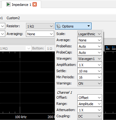
The Options drop-down menu provides the user with the following configuration parameters for the Impedance Analyzer Instrument tool:
- Scale: Logarithmic or Linear
- Average: Averages the plotted data over the chosen number of samples
- ProbeRes: Accommodates for different oscilloscope probe resistances
- ProbCap: Accommodates for different oscilloscope probe capacitances
- Wavegen: Selects Wavegen Channel 1 or Wavegen Channel 2 as signal source
- Amplification: Attenuates or amplifies acquired data by factors of 10
- Settle: Characterizes the time window between sampled data
- Min Periods: Characterizes the minimum number of sampling periods by powers of 2
- Warnings: Choose whether to display warnings like “Resistor too low” or not
Scope Channel 1 and Channel 2 Options:
- Offset: Apply DC offset to a Scope channel
- Range: Set range for Scope by input signal amplitude or a set voltage
- Attenuation: Attenuate or amplify Scope data
- Coupling: AC or DC couple the respective channel
- Bandwidth: Enable or disable bandwidth limitation
- Impedance: Not available

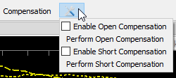
3.2.8 Compensation
Compensation helps calibrate the Impedance Analyzer. This becomes more useful when working with higher frequencies, using higher reference resistor values, and detecting smaller capacitances and inductances.
Image A shows the Compensation tools icon selected, which allows the user to enable and perform open and short circuit compensation. Image B shows the Compensation configuration window shown when “Compensation” is clicked. This window provides some parameters found on the Control Bar as well as buttons for open/short compensation for multiple reference resistor options.
These reference resistor values can also be changed in this window and reflected in the Control Bar's Resistor drop-down menu. This is useful when the reference resistor value is not exactly it's marked value. When compensation is performed, values are stored for each reference resistor value over the specified frequency range. If the resistor values or frequency range changes, this compensation must be performed again.
Performing Compensation: First, measure the reference resistors actual value with a precise multimeter and enter that value into the Compensation window text field under “Resistor”. To perform Open Compensation, disconnect the DUT terminals from the impedance analysis topology, leaving the DUT an open circuit. To perform Short Compensation, short the DUT terminals while remaining in the impedance analysis topology chosen.
3.3 File Menu
The File drop down menu has these options available to the user:
- New Impedance: Create new Impedance Analyzer Instrument window (Empty) or copy the current Impedance Analyzer Instrument and its settings into a new window (Clone)
- Open Project: Open a previously saved Waveforms workspace
- Save Project: Save the current Waveforms workspace
- Export: Export plotted/acquired data and/or images of the plot planes
- Close Impedance: Close the current Impedance Analyzer Instrument tool window
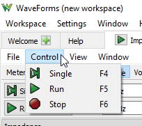
3.4 Control Menu
The Control menu contains the acquisition controls for the user that are also available in the Control Bar:
- Single: Run a single acquisition of the Impedance tool
- Run: Run a repeating acquisition of the Impedance tool
- Stop: Stop acquisition
3.5 View Menu
The View menu provides the same plot/window toggling options discussed in Section 3.1.2 (Analyzer Mode) but with two additional window options:
- Time: shows a time domain plot of the DUT
- Notes: A text editor pane for user notes when using the Impedance Analyzer Instrument
3.6 Window Menu
The Window menu provides three main options to the user:
- Help: A link to the WaveForms help menu
- Waveforms: A link to the WaveForms Welcome window
- Links to other Waveforms tools that are currently open
Other Resources
For more guides on how to use the Digilent Test and Measurement device, return to the device's Resource Center, linked from the Test and Measurement page of this wiki.
For more information on WaveForms, visit the WaveForms Reference Manual.
For technical support, please visit the Test and Measurement section of the Digilent Forums.


