Using the Waveform Generator
Introduction
Waveform Generators are used to apply specified analog signals to circuits, anything from DC signals, sine waves of varying frequencies, AM/FM modulated signals, and more. This guide explains the use of the Waveform Generator instrument in WaveForms. This instrument is also referred to as the Wavegen.
Prerequisites
- A Digilent Test & Measurement Device with Analog Input and Output Channels:
- A Computer with WaveForms Software Installed
Guide
1. Opening the Wavegen
1.1
Plug in the Test & Measurement Device, then start WaveForms and make sure the device is connected.
If no device is connected to the host computer when WaveForms launches, the Device Manager will be launched. Make sure that the device is plugged in and turned on, at which point it will appear in the Device Manager's device list (1). Click on the device in the list to select it, then click on the buffer size (2). Click the Select button (3) to close the Device Manager.
Note: “DEMO” devices are also listed, which allow the user to use WaveForms and create projects without a physical device.
Note: The Device Manager can be opened by clicking on the “Connected Device” button in the bottom right corner of the screen (4.), or by selecting “Device Manager” from the “Settings” menu at the top of the screen.

1.2
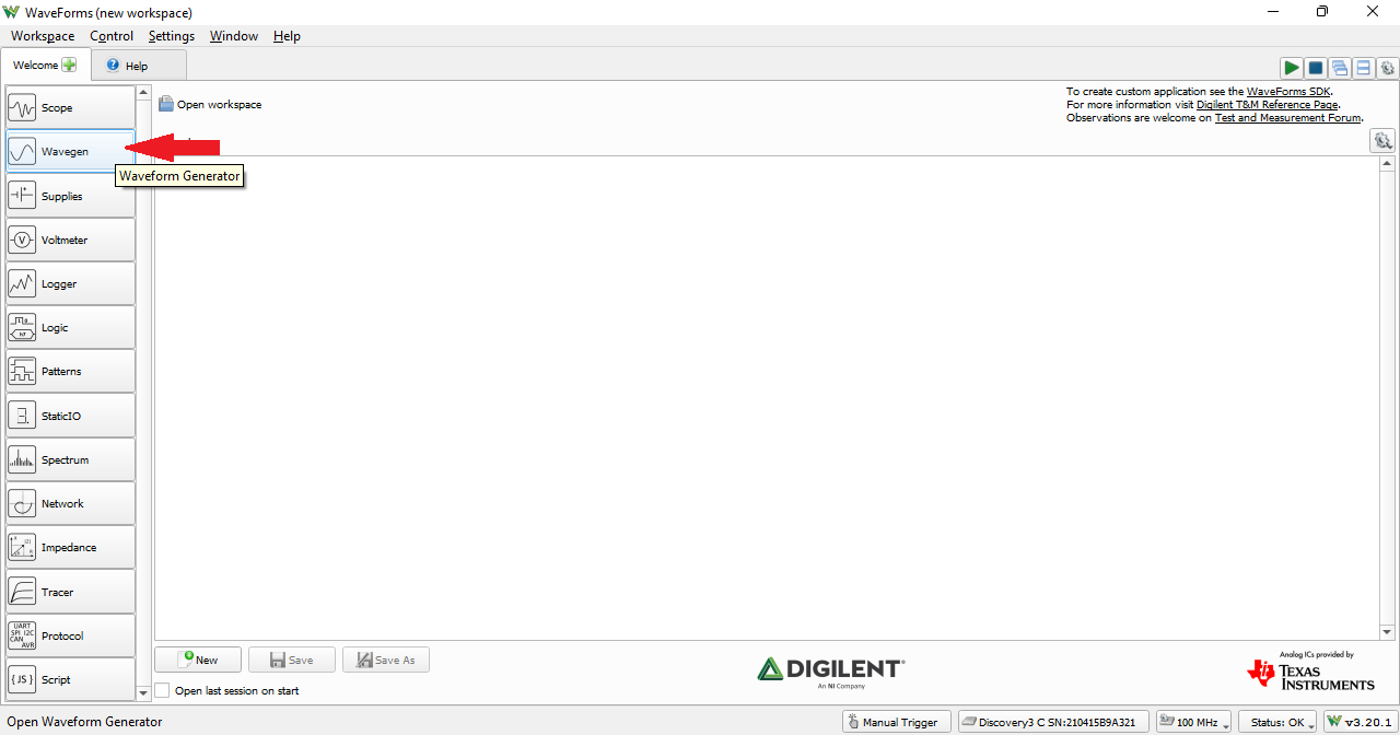
Once the Welcome page loads, in the instrument panel at the left side of the window, click on the Wavegen button to open the Waveform Generator instrument.
1.3
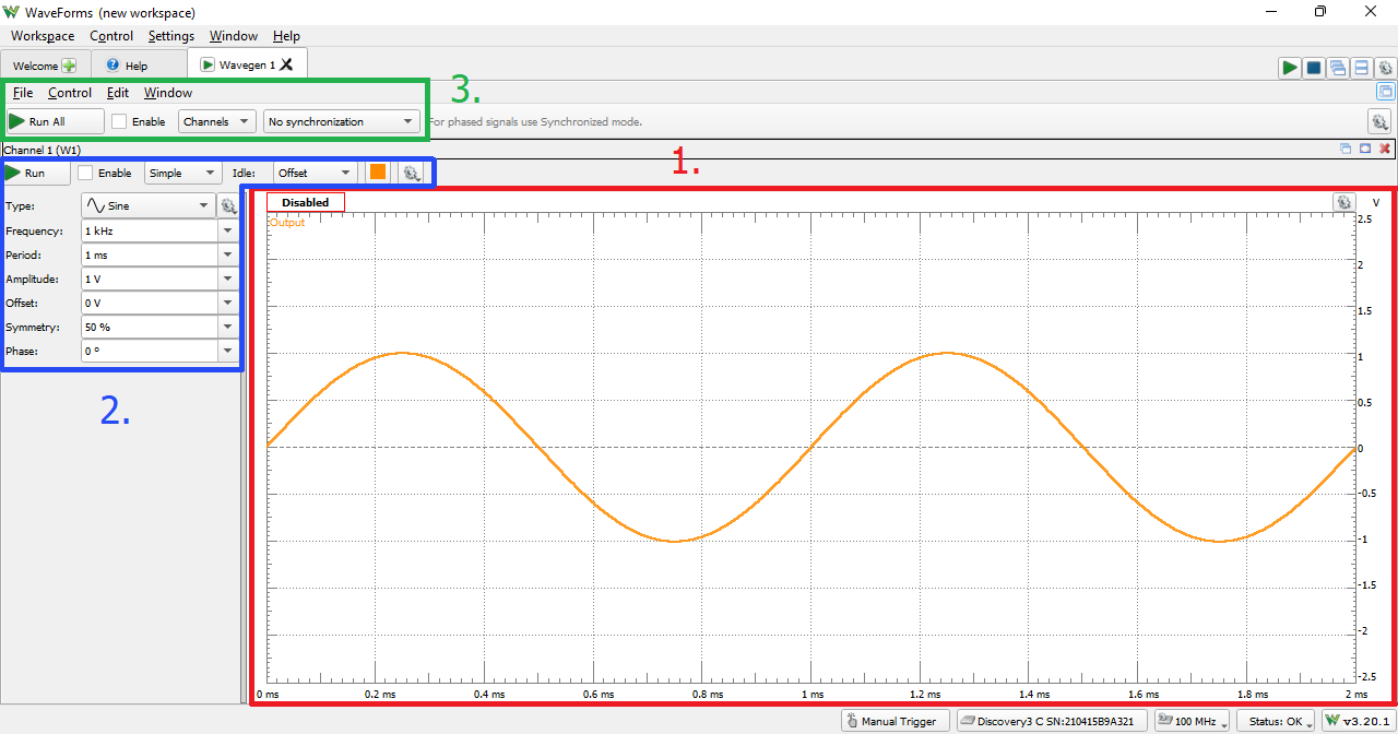
Once the Wavegen instrument opens, the window contains the preview plot (1.) showing what the expected waveform is, the configuration panel (2.) left of the preview, and the control toolbar (3.) above both.
2. Using the Wavegen
This section details how to configure and run the Wavegen instrument
2.1 Hardware Setup
To demonstrate the capabilities of the Waveform Generator instrument, the Scope instrument is used to visualize the Waveform Generator's output signal. This step describes setting up a simple loopback circuit that connects the Test and Measurement device's Waveform Generator and Oscilloscope.
MTE Cables
If your Digilent Test and Measurement device supports MTE cables for analog output, open the dropdown below for instructions on setting up a loopback circuit with them.
- MTE Cable Loopback
-
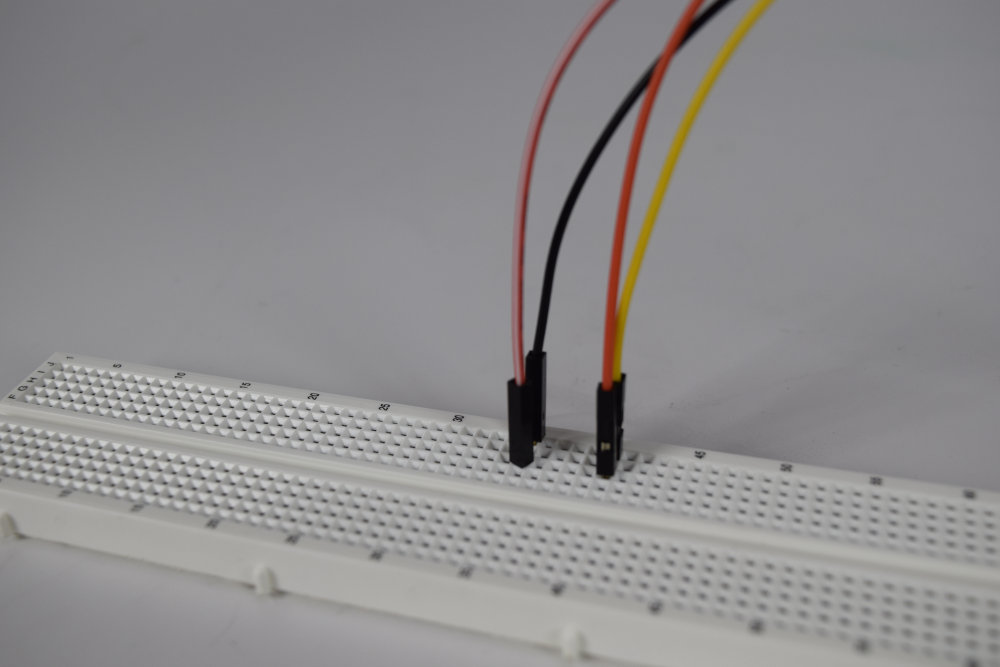
Connect the Test & Measurement device's Oscilloscope Channel 1 pin (orange wire) to the device's Wavegen Channel 1 output pin (yellow wire). For devices that use differential input channels, such as the Analog Discovery Studio with MTE cables, make sure to connect the Oscilloscope Channel 1 negative pin (orange wire with white stripes) to the ground pin associated with Wavegen Channel 1 (black wire).
BNC Oscilloscope Probes
If your Digilent Test and Measurement device supports BNC cables, select your device below for instructions on setting up a loopback with them.
- Analog Discovery 3 or Analog Discovery 2 with BNC Adapter
-
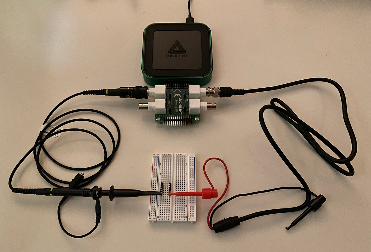
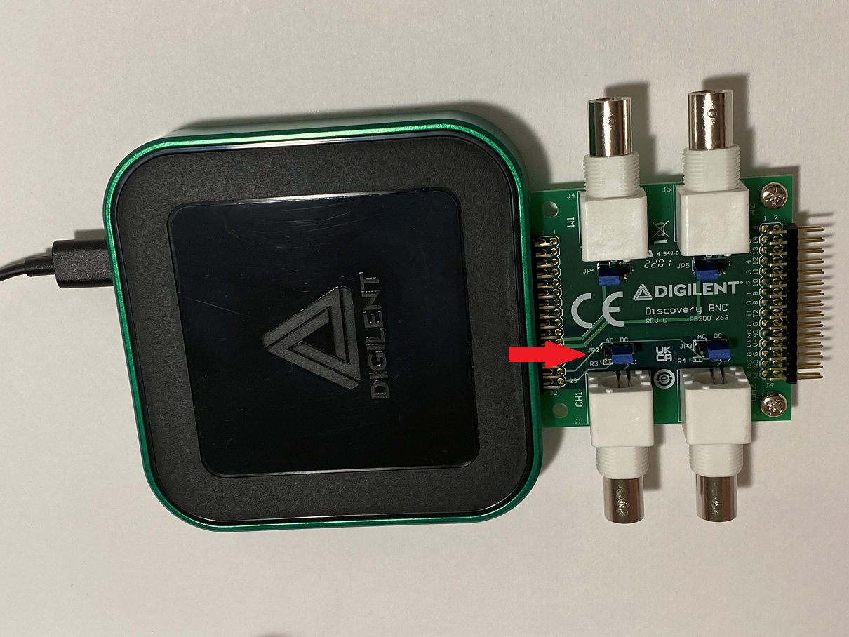
Connect the BNC Adapter to the Analog Discovery 3, as shown in the image to the right. Next, connect BNC cables to the Test and Measurement device's Oscilloscope Channel 1 BNC Connector and Wavegen Channel 1 BNC Connector. Connect the cables' probes to one another. Check the input probe's attenuation factor, as it will be used later to set up the software.
Note: For this demo, the Scope and Wavegen ground wires are not connected because the two channels share the same ground. While BNC Probes are single-ended (as is the Waveform Generator hardware), a connected circuit must still share a common ground with the device. No more than one ground should be connected, to avoid the creation of ground loops that may introduce excess noise to measurements.
Note: When using BNC Probes, make sure to take note of the probes' bandwidth. When probes are used with an oscilloscope, the achievable bandwidth is limited by both the probes and the scope. For example, using 1 MHz probes will limit the bandwidth to 1 MHz, even if it's below the Test and Measurement device's specified maximum.
- Analog Discovery Studio
-
Connect BNC cables to the Test and Measurement device's Oscilloscope Channel 1 BNC Connector and Wavegen Channel 1 BNC Connector. Connect the cables' probes to one another. Check the input probe's attenuation factor.
Note: For this demo, the Oscilloscope and Wavegen ground wires are not connected because they share the same ground. While BNC Probes are single-ended (as is the Waveform Generator hardware), a connected circuit must still share a common ground with the device. No more than one ground should be connected, to avoid the creation of ground loops that may introduce excess noise to measurements.
Note: When using BNC Cables, make sure to take note of the probes' bandwidth. When probes are used with an oscilloscope, the achievable bandwidth is limited by both the probes and the scope. For example, using 1 MHz probes will limit the bandwidth to 1 MHz, even if it's below the Test and Measurement device's specified maximum.
Note: The Analog Discovery Studio's Wavegen BNC connectors are DC coupled and have an output impedance of 75Ω.
Note: The Analog Output signal produced by the Waveform Generator is available on both the BNC and MTE cables at the same time.

- Analog Discovery Pro (ADP2230)
-
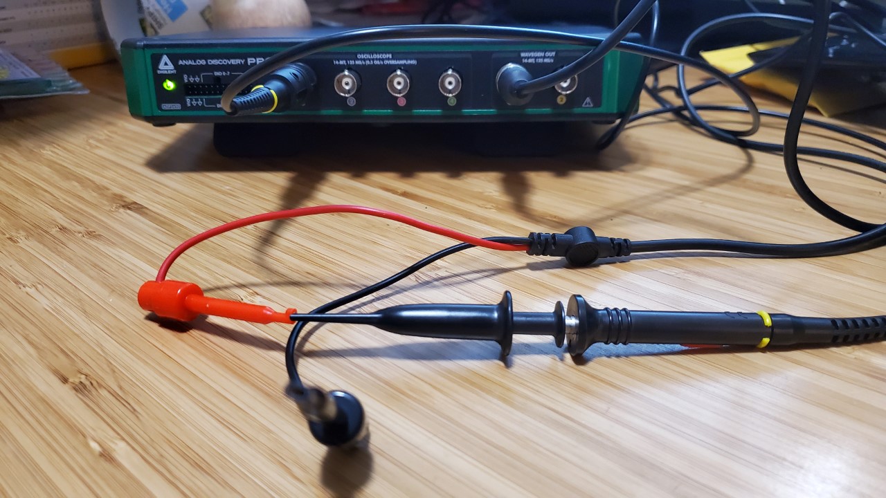
Connect a BNC oscilloscope probe to the Analog Discovery Pro's Oscilloscope Channel 1 connector and a set of BNC minigrabbers to its AWG Channel 1 connector. Connect these as pictured, to form a loopback circuit. Check the input probe's attenuation factor, as it will be used later to set up the software.
Note: For this demo, the Scope and AWG ground wires are not connected because the two channels share the same ground. While BNC Probes are single-ended (as is the AWG hardware), a connected circuit must still share a common ground with the device. No more than one ground should be connected, to avoid the creation of ground loops that may introduce excess noise to measurements.
Note: When using BNC Probes, make sure to take note of the probes' bandwidth. When probes are used with an oscilloscope, the achievable bandwidth is limited by both the probes and the scope. For example, using 1 MHz probes will limit the bandwidth to 1 MHz, even if it's below the Test and Measurement device's specified maximum. To take full advantage of a probe's bandwidth, the 10X attenuation setting should be used.
- Analog Discovery Pro (ADP3450/ADP3250)
-
Connect a BNC oscilloscope probe to the Analog Discovery Pro's Oscilloscope Channel 1 connector and a set of BNC minigrabbers to its Wavegen Out Channel 1 connector. Connect these as pictured, to form a loopback circuit. Check the input probe's attenuation factor, as it will be used later to set up the software.
Note: For this demo, the Scope and Wavegen Out ground wires are not connected because the two channels share the same ground. While BNC Probes are single-ended (as is the Waveform Generator hardware), a connected circuit must still share a common ground with the device. No more than one ground should be connected, to avoid the creation of ground loops that may introduce excess noise to measurements.
Note: When using BNC Probes, make sure to take note of the probes' bandwidth. When probes are used with an oscilloscope, the achievable bandwidth is limited by both the probes and the scope. For example, using 1 MHz probes will limit the bandwidth to 1 MHz, even if it's below the Test and Measurement device's specified maximum. To take full advantage of a probe's bandwidth, the 10X attenuation setting should be used.
- Analog Discovery Pro (ADP5250)
-
Connect a BNC oscilloscope probe to the Analog Discovery Pro's Oscilloscope Channel 1 connector and the BNC minigrabbers to the AWG Channel 1 connector on the front of the ADP5250. Connect these as pictured, to form a loopback circuit. Check the input probe's attenuation factor, as it will be used later to set up the software.
Note: For this demo, the Scope and AWG ground wires are not connected because the two channels share the same ground. While BNC Probes are single-ended (as is the Waveform Generator hardware), a connected circuit must still share a common ground with the device. No more than one ground should be connected, to avoid the creation of ground loops that may introduce excess noise to measurements.
Note: When using BNC Probes, make sure to take note of the probes' bandwidth. When probes are used with an oscilloscope, the achievable bandwidth is limited by both the probes and the scope. For example, using 1 MHz probes will limit the bandwidth to 1 MHz, even if it's below the Test and Measurement device's specified maximum.

2.2 Set Up the Oscilloscope
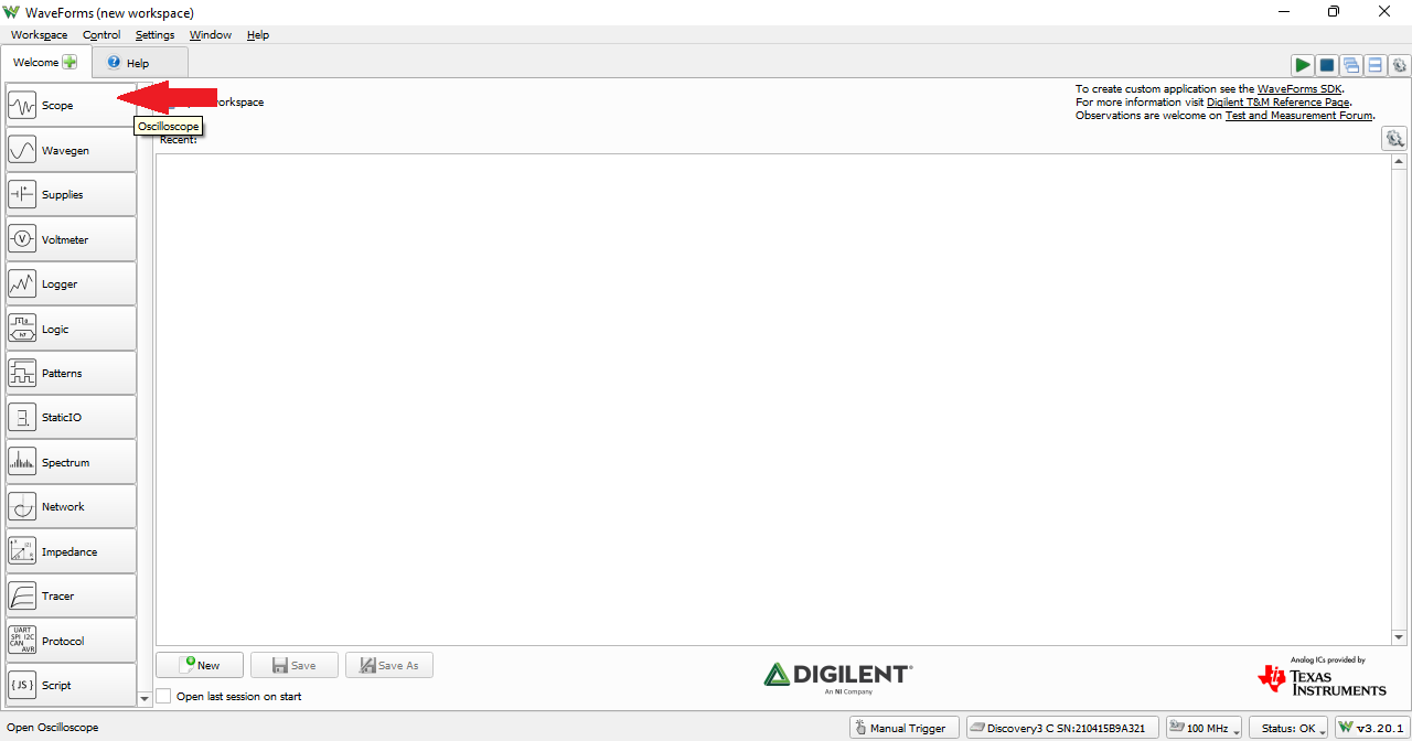
With the loopback circuit set up, return to WaveForm's Welcome page by clicking on the Welcome tab at the top of the screen. In the Welcome page, open the Scope instrument, then click the “Run” button ( ) in the control bar near the top of the window to begin measuring the signal.
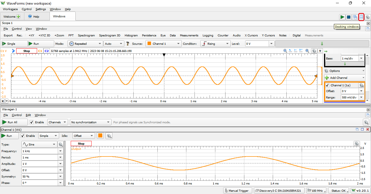
Next, the Wavegen and Scope instruments will be docked so that any changes to Wavegen settings can immediately be viewed in the Scope.
In order to show both the Wavegen and the Scope instruments on the screen at once, click on the Docking Windows button ( ) in the top right corner of the screen.
Note: To return to the default tabbed view later, click on the “Tabbed Windows” button ( ) adjacent to the Docking Windows button.
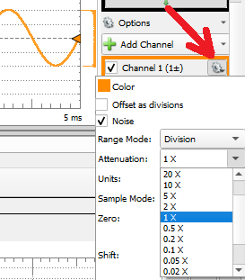
If using a BNC cable for Analog Input, click the dropdown below. No additional software settings are required to use BNC cables for Analog Output.
- Set the BNC Cable Attenuation Factor
-
Regardless of the device, if BNC cables are used for input, make sure that the attenuation factor setting in WaveForms for Oscilloscope Channel 1 (pictured to the right) matches the setting of the probe.
2.3 Configure Signal Type
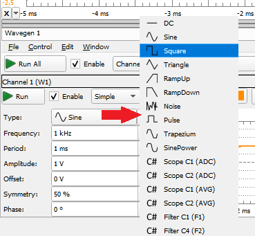
Begin by changing the signal type. Click the Type drop-down and choose Square.
2.4
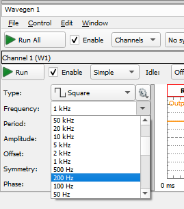
The frequency is configured by selecting the value from the Frequency drop-down list, or by clicking into the field and manually typing it in (including units and an SI suffix). Set the frequency to 200 Hz.
2.5
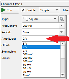
Configuring the amplitude is similar to changing frequency. Proceed by setting the amplitude to 2 V.
2.6
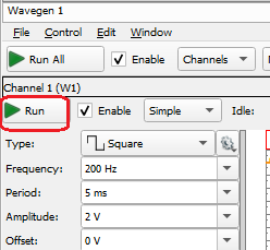
Click the Run button ( ) in the control bar near the top of the window to begin output the signal.
2.7
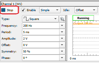
Back in the Wavegen instrument, click Stop ( ) to turn off the output signal, leaving the channel enabled and idle. Clicking Stop All will stop all active channels while clicking “Stop” stops only that particular channel.
Note: An idle channel will still output some amount of voltage, which is determined by the offset parameter by default. Unchecking enable at any point will stop the signal if it is running, disable the channel and set its output voltage to 0 V.
Digilent Oscilloscopes feature the ability to select from a range of sample rates, which affects many instruments. Click the dropdown below to learn how to use this feature.
- Modify the Digilent Oscilloscope System Clock Rate
-
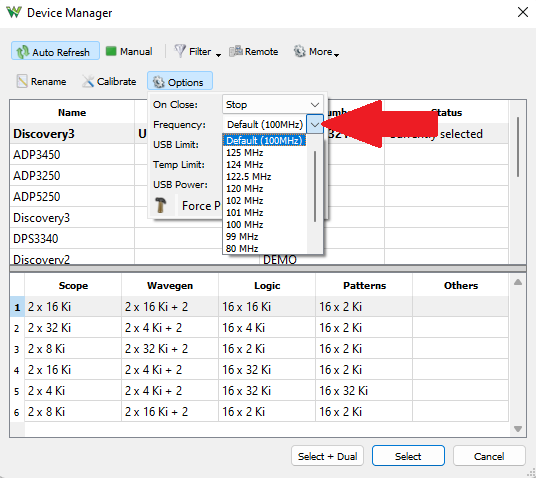
To access this setting, first open the Device Manager, which can be found in WaveForms' “Settings” menu.
The system clock rate itself can be changed by opening the Options dropdown, while the Digilent device is selected in the list of devices. By changing the selection in the “Frequency” dropdown, the clock rate is changed. By increasing the system's clock rate in this way, the Waveform Generator, Oscilloscope, Logic Analyzer, Pattern Generator, and others, are made able to take in or put out samples at a rate of up to 125 MHz.
Note: Changing the system clock rate changes the set of sample rates that can be achieved by the Digilent Oscilloscope's Digital I/O pins. Achievable rates with either selection are integer divisions of the system sample rate. For example, a 62.5 MS/s sample rate is achievable in the Logic Analyzer when the frequency is set to 125 MHz, and a 25 MS/s sample rate when the frequency is 50 MHz.
Note: Analog Discovery Pro (ADP5250) Wavegen Output Filter
The Analog Discovery Pro (ADP5250) features a switchable filter on the AWG output. Click the dropdown below to learn how to use this feature.
- Enable or Disable the ADP5250's AWG Filter
-
This filter can be enabled or disabled through the use of the dropdown on the right side of the control toolbar. It can be set to Auto, On, or Off.

Note: Using Multiple Instruments
The Waveform Generator instrument can be used with other WaveForms instruments. Using multiple instruments at the same time is helpful in a wide variety of situations. One example would be to use the Waveform Generator to stimulate a circuit under test, the Power Supplies to provide power to the circuit and view the response with the Oscilloscope, all at the same time. More information on how instruments can be operated together can be found in the Using Cross Triggering guide.
It should be noted that the Analog Output channels cannot be shared by multiple instruments. When the Waveform Generator is enabled, any other instruments using the Analog Output channels are disabled. Other instruments that use the Analog Output channels include the Network Analyzer, and Impedance Analyzer.
3. Wavegen UI Overview
This sections walks through the different controls and features present in the Wavegen instrument
3.1 The Control Toolbar
The control toolbar contains menus and control interfaces used to configure the Wavegen instrument.

File contains options to start a new Wavegen instance, open, or save a Wavegen project for sharing or reuse of the configuration, or export the current Wavegen data as an image or raw data file formatted as a *.csv, *.txt or *.tdms.

Control contains the Run All and Stop All actions.

Channels allows the user to open or close wavegen channels for configuration.

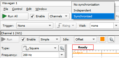
The Synchronization dropdown allows the user to select how the Wavegen Channels operate in regards to each other. Selecting Synchronized enables the use of triggers to control the output of the channels. More information on the use of triggers within WaveForms can be found in this Wiki's Using Cross Triggering and Using External Triggers guides.
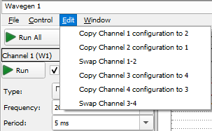
Edit lets the user copy or swap output signal configurations between available channels.
3.2 The Preview Plot
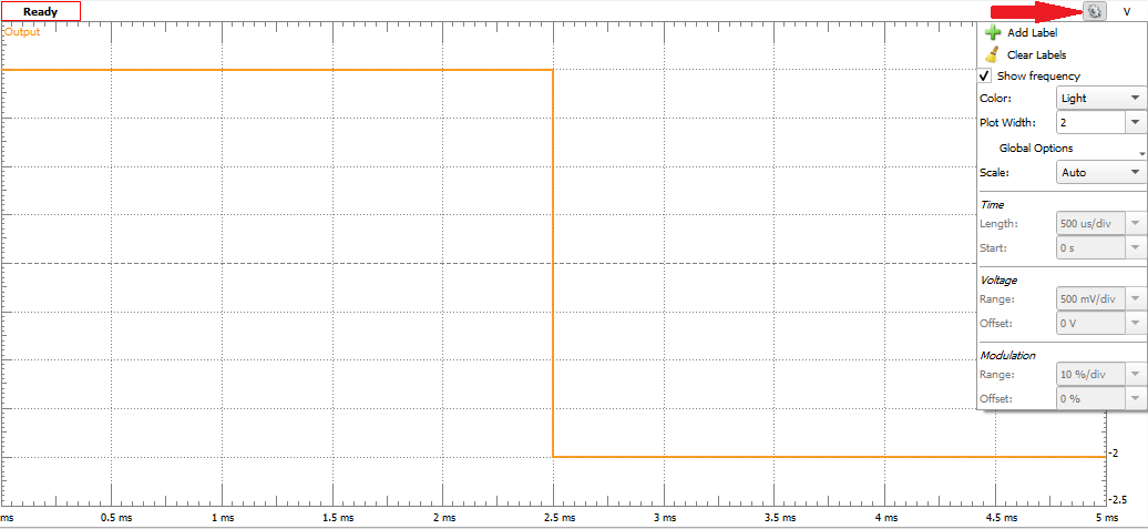
The preview plot displays what the waveform output will be. As the waveform parameters are changed in the configuration panel, the preview plot will update to reflect the changes.
Preview plot graphical settings can be changed by clicking on the Gear icon ( ) in the top right.
3.3 The Configuration Panel
Configuration of the output waveform is done using the configuration panel. There are several different sets of configuration options, which can be selected with the drop-down to the right of the Enable checkbox, labeled “Simple” by default
The “Simple” view accesses the signal type, frequency, amplitude, offset, signal symmetry and phase as drop-down menus. The other panels either allow you to configure the signal parameters in a different manner, or allow for more complicated signal types.

The “Basic” panel allows configuration of the signal parameters that the Simple panel exposes but does so using sliders. Min and max values can be defined or adjusted via a slider. The usefulness of this panel comes when one is trying to make minute adjustments to the output signal.
In this panel, the list of waves seen at the left side of the window can be changed by adding, importing, editing, or removing waves through the use of the buttons at the top of the list. When adding or editing a wave, the wave can be defined through several different methods, including through mathematical functions, through a data file (including CSV, TXT, and various audio files), or as a variant of one of the default functions. Note that the default set of waves cannot be edited or removed.

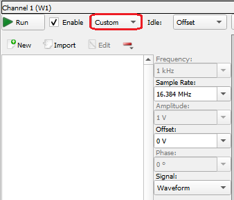
The “Custom” panel allows you to build the output signal by combining pieces of pre-defined signals. This is may be done by defining the mathematical representation of the signal using JavaScript syntax, providing the output value of the signal at discrete steps, or by importing a saved waveform file. You may also draw the signal free hand by clicking and dragging in the preview plot of the Custom window.
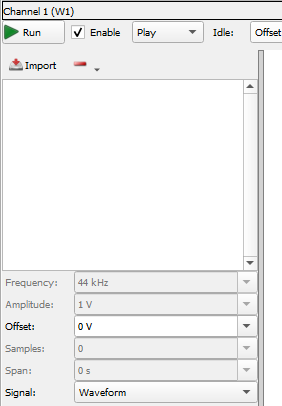
The “Play” panel allows the user to import then play back a saved file, including audio files. Supported formats are *.csv, *.txt, *.mp3, *.wav, *.wmv and *.avi.
For devices that have a headphone jack, the Wavegen Channel outputs are always available through the connector.
The “Sweep” panel is used to play a dynamic signal where the frequency and amplitude changes within a set amount of time. The sweep panel provides all of the same configuration options as the simple configuration panel, with the addition of a linear frequency and/or amplitude sweep.

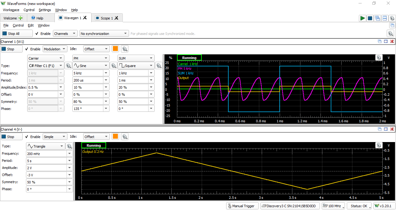
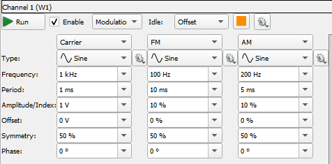
The “Modulation” panel allows the user to create amplitude- and frequency-modulated signals. The first column defines a high frequency carrier signal, the second column defines another signal that modulates the frequency of signal of the carrier, the third lets modulate the amplitude of the carrier, with a checkbox above each column to enables/disables that modulation.
Next Steps
For more guides on how to use the Digilent Test & Measurement Device, return to the device's Resource Center, linked from the Test and Measurement page of this wiki.
If voltage values output by the Wavegen are significantly different from expected, please calibrate the device by following the Calibration Guide.
For more information on WaveForms visit the WaveForms Reference Manual.
For technical support, please visit the Test and Measurement section of the Digilent Forums.

