This is an old revision of the document!
Using the Eclypse Z7 and Zmod Scope with the Zmod Library
Under Construction
 add image
Description
Broadly describe what the demo does here. If the demo was originally documented elsewhere, this section can be pulled directly from the introduction to the Github README, or from an existing wiki page.
This demo uses the Zmod Scope 1410, the initial release of the Zmod ADC IP cores (ZmodADC1410Controller and AXI_Zmod_ADC1410), and the Zmod ADC1410 software library to perform 10 us captures of an incoming signal. Both baremetal and PetaLinux-based projects are provided.
Inventory
- Eclypse Z7 with a MicroUSB Programming Cable and external Power Supply
- a Zmod Scope installed in the Eclypse's Zmod A port
- Important! Only the Zmod Scope 1410-105 is supported
- Vivado and Xilinx SDK installations compatible with the latest release of this demo (2019.1)
- See Getting Started with Vivado for installation instructions.
- PetaLinux Installation compatible with the latest release of this demo (2019.1)
- See Xilinx's PetaLinux Tools Documentation (2019.1) (UG1144) for installation instructions.
- Only required if you want to rebuild the PetaLinux image
- Serial Terminal application to receive messages printed by the demo
- See Installing and Using a Terminal Emulator for more information.
Download and Usage Instructions
most of this needs rewritten, potentially copy paste from https://digilent.com/reference/zmod/zmodbaselibraryuserguide and https://digilent.com/reference/programmable-logic/eclypse-z7/git
First and foremost, releases - consisting of a set of files for download - are only compatible with a specific version of the Xilinx tools, as specified in the name of the release (referred to as a release tag). In addition, releases are only compatible with the specified variant of the board. For example, a release tagged “20/DMA/2020.1” for the Zybo Z7 is only to be used with the -20 variant of the board and Xilinx tools (Vivado and Vitis) version 2020.1.
The latest release version for this demo is highlighted in green.
In a specific demo's page, table rows should only be created for releases that have a README that explains the use of that release. The Board Variant column should be excluded if there are no variants of the board. Release links can be found by navigating to the Releases page of a Github repo and selecting a single release. The latest release for each variant is highlighted in green, as seen in the table below.
| Release Tag | Release Downloads | Setup Instructions |
|---|---|---|
| (tag) | Release ZIP Downloads | See Using the Latest Release, below |
Note for Advanced Users: All demos for the (Board) are provided through the (Board) repository on Github. Further documentation on the structure of this repository can be found on this wiki's Digilent FPGA Demo Git Repositories page.
Instructions on the use of the latest release can be found in this dropdown:
- Using the Latest Release
-
Note: This workflow is common across many Digilent FPGA demos. Screenshots may not match the demo you are working with.
Important: These steps are only to be used with releases for Xilinx tools versions 2020.1 and newer. Older releases may require other flows, as noted in the table of releases.
First, download the '*-hw.xpr.zip' and “Software source archive” files from the demo release, linked above. Note that the hardware is included in the Assets list, while the software is linked from the description of the release.
The hardware (-hw) archive contains the Vivado project used to build the hardware platform for this demo. The project can be opened, modified, and used to update the hardware platform later if so desired, but this is optional. The software archive contains the software sources, hardware description file (XSA), and a set of scripts that can be used to rebuild the workspace.
Both files should be extracted.
Note: You may notice “-sw” archives in the release's downloads list. These importable archives should be ignored - a bug in Vitis 2020.1 prevents their use in some situations, and as such, the scripted method here is to be used instead.
- Recreate a Vitis Workspace from Source
-
Important: When selecting a workspace to open Vitis into, the use of the extracted software archive's “ws” folder is recommended. The use of this folder simplifies the process of invoking the script that recreates the projects.
Select the dropdown corresponding to your operating system, below.
- Windows
-
Open Vitis through the start menu or desktop shortcut created during the installation process.

- Linux
-
Open a terminal and run the following commands. The install path is /opt/Xilinx by default.
source <install_path>/Vitis/2020.1/settings64.sh
vitis
Note: Regardless of OS, if Vivado is open, Vitis can also be launched through the Tools → Launch Vitis toolbar option.
Upon launching Vitis, a dialog will appear where a workspace must be chosen. The workspace is the directory where all of the projects and files for the application being developed will live. If a folder that does not currently exist is chosen, it will be created. Choose a workspace and click Launch to finish launching Vitis.

With Vitis open, in the menu bar at the top of the window, use the Xilinx → XSCT Console option to launch the Xilinx Software Command-line Tool.

In the XSCT Console, if you used the software archive's ws folder, enter the command below to run a script that recreates each of the projects and platforms associated with the demo from their sources.
source [getws]/../src/checkout.tcl
If you did not use the ws folder, find the path to the extracted archive, and enter the commands below. Note that all slashes in the path must be forward slashes (“/”) or the entire path must be enclosed in curly braces (“{}”).
source (path to software)/src/checkout.tcl
The checkout process may some time, though not more than a few minutes, as the projects are recreated and built. When complete, the “xsct%” prompt will reappear.

- Set up the (Board)
-
Provide any additional demo-specific setup that needs to occur prior to programming here. This may include connecting a serial console, connecting additional hardware, etc.
- Launch a Vitis Application
-
Make sure your board is set to boot from JTAG before it's powered on. JTAG programming can override other boot modes on some devices, but it's easier to tell when a project is programmed into the board if there isn't already one in there.
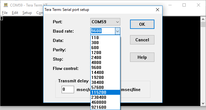
First, many applications require that a serial console is connected to the board, so that standard output (from print statements) can be viewed. For this purpose, a serial terminal should be used. Use a serial terminal application to connect to the board's serial port. Unless otherwise stated, Zynq designs use a baud rate of 115200 and Microblaze designs with an AXI UART Lite IP use a baud rate of 9600. Flow control should be set to NONE.
Note: While Vitis has a built in serial terminal included in its Debug view, it sends characters to a board on a line-by-line basis. Some software examples require the use of character-by-character reception of data. Tera Term or PuTTY are recommended if you are not sure what will work.
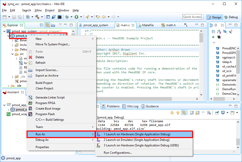
In the Explorer pane at the left side of the screen, right click on the application or system project that is to be run, and select Run as → 1 Launch on Hardware (Single Application Debug). The FPGA will be programmed with the bitstream, the ELF file created by the software build is loaded into system memory, and the application project will begin to run. You will need to click back over to the Vitis Serial Terminal from the Console tab.
Note: Once the project has been run at least once, you can use the green run button (
 ) in the toolbar at the top of the screen to program the board instead.
At this point, the demo is now running on your board. Refer to the Description section of this document for more information on what it does. alternatively, if more information is required, add an additional outliner dropdown here. Warnings about potential damage to the board should be placed here regardless.
Additional steps beyond here present how you can use the other archive provided in the release, containing the hardware project, to rebuild the Vivado project, and use a newly exported XSA file to update the platform in Vitis.
In order to modify and switch out the hardware platform for a baremetal demo, you should first open the Vivado project from the release. Extract the previously downloaded '*.xpr.zip' file.
- Open a Block Design Project in Vivado
-
Launch Vivado
Select the dropdown corresponding to your operating system, below.
- Windows
-
Open Vivado through the start menu or desktop shortcut created during the installation process.

- Linux
-
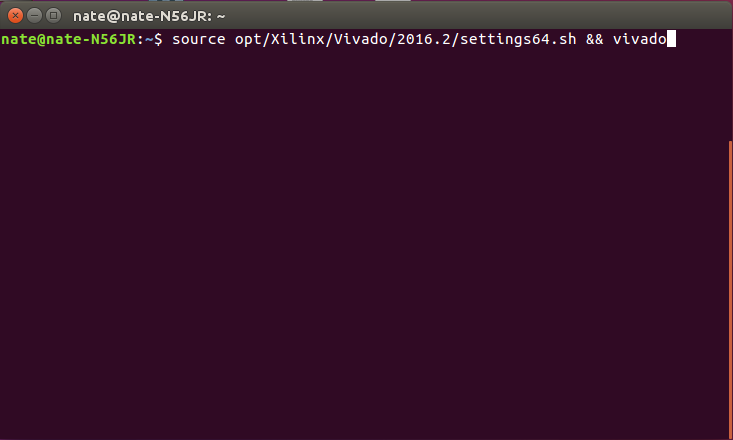
Open a terminal, and change directory (cd) to a folder where log files for your Vivado session can be placed, then run the following commands:
source <install_path>/Vivado/<version>/settings64.sh
vivado
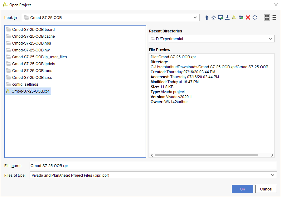
In Vivado's welcome screen, use the Open Project button to navigate to and open the XPR file contained in the folder the release was extracted into.
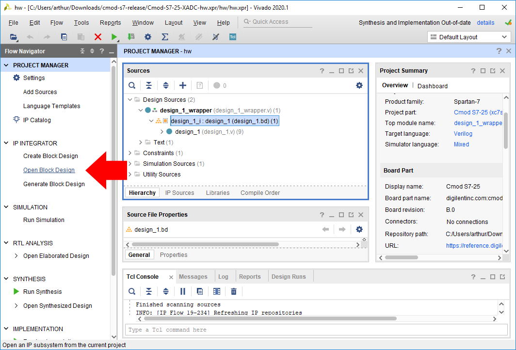
The project's block diagram, which contains the design, with all of the existing components and their connections, can be opened by either double-clicking on the “*.bd” file in the sources pane (which also includes other source files, such as constraints), or by clicking the Open Block Design button in the Flow Navigator pane.
Making changes to the design is out of the scope of this particular document. More information on how to use IP Integrator to create or modify a project can be found through Getting Started with Vivado and Vitis for Baremetal Software Projects. The remainder of this document will discuss how to generate a bitstream, export a new hardware platform, and load it into Vitis.
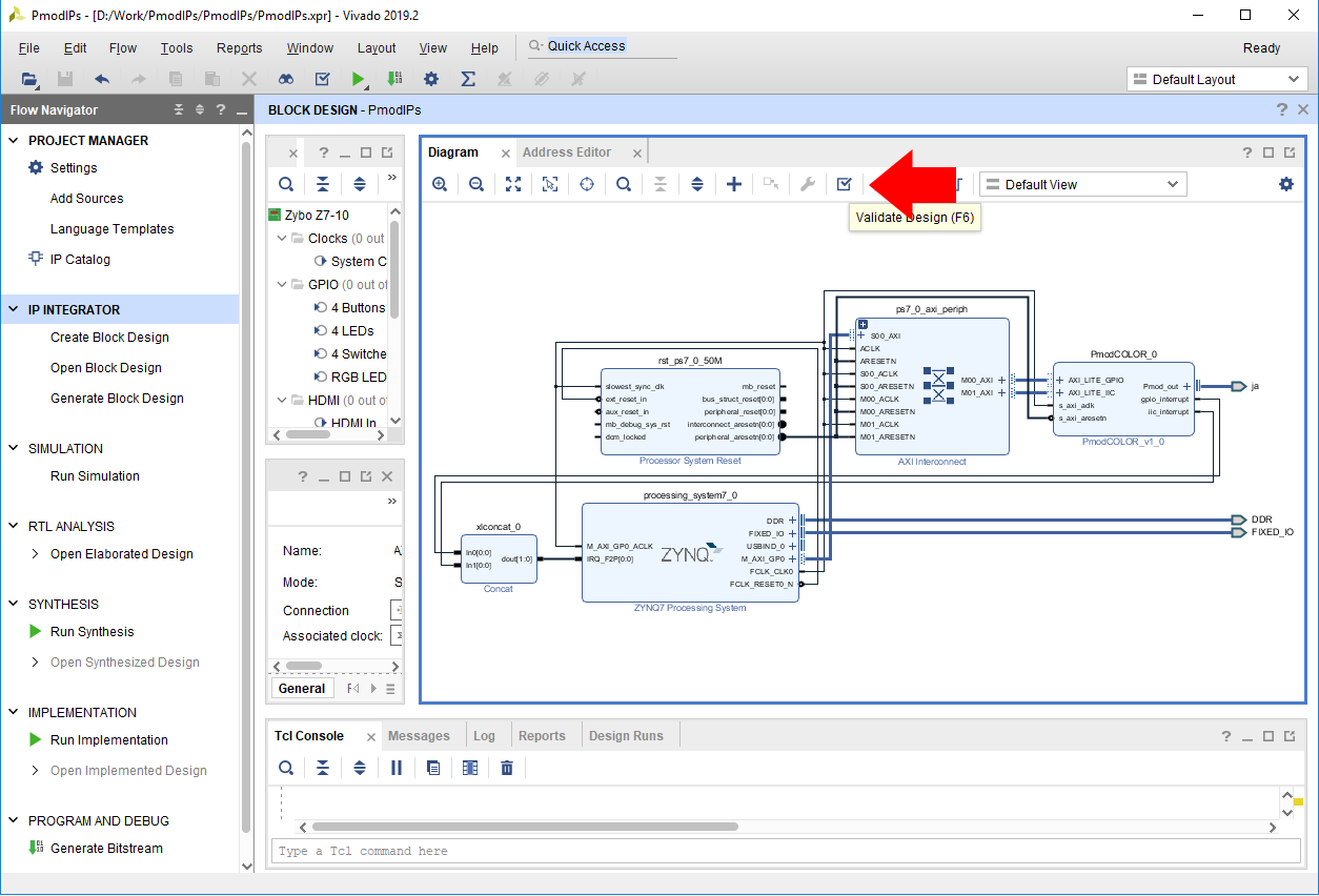
Before the Vivado project can be built, the block design must be validated. This step runs an automatic check of the block design to see if there are any potential issues with it. Click the Validate Design button (
 ) in the Diagram pane's toolbar (or press the F6 key).
If the design has issues, a dialog will pop up that lists them. It should be noted that most Warnings can be ignored, as can some Critical Warnings. These issues can also be viewed in the Messages tab of the pane at the bottom of the window.
If there are no issues, a dialog will pop up that will tell you so. Click OK to continue.
Note: Some Zynq boards may produce critical warnings at this stage relating to PCW_UIPARAM_DDR_DQS_TO_CLK_DELAY parameters. These warnings are ignorable and will not affect the functionality of the project. See the Hardware Errata section of your board's reference manual for more information.
- Build a Vivado Project
-
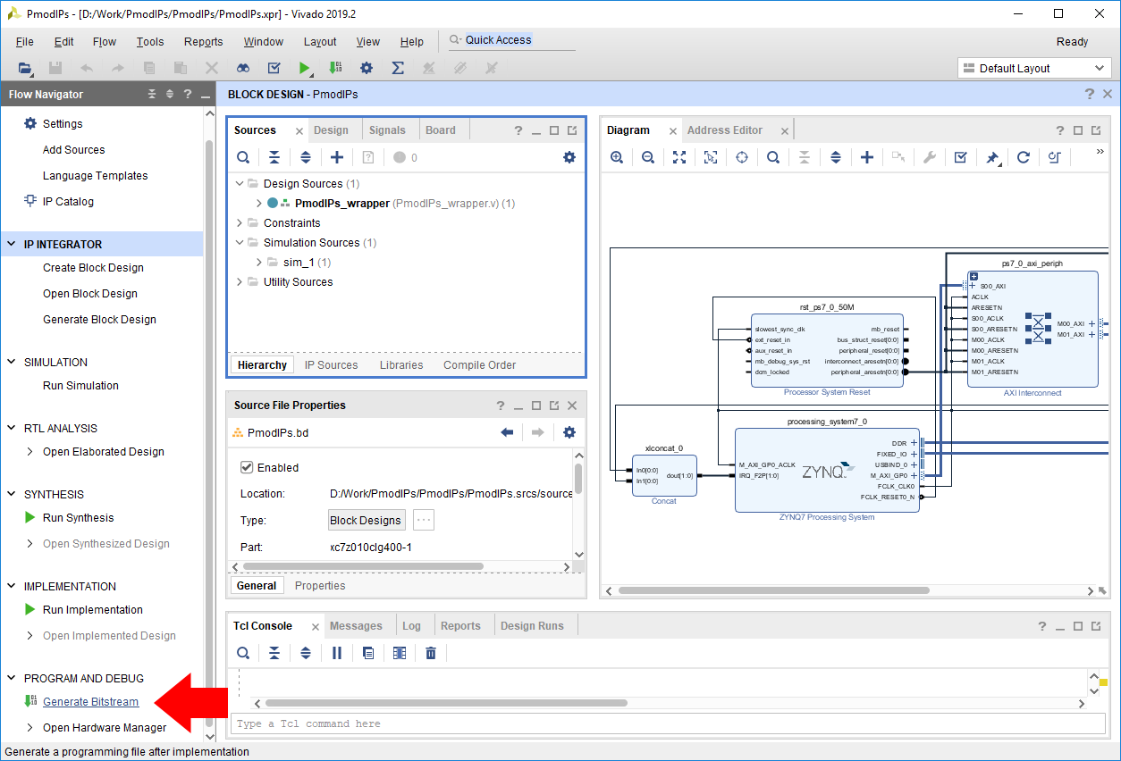
At this point, the Vivado Project is ready to be built, by running it through Synthesis and Implementation, and finally generating a bitstream. Click the Generate Bitstream button in the Program and Debug section of the Flow Navigator pane at the left side of the window.
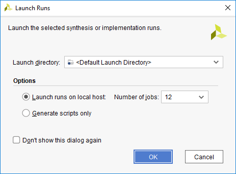
A dialog will pop up with several options for how Synthesis and Implementation should be run. Most should be left as defaults. Of particular importance is the Number of jobs dropdown, which is used to specify how much of the resources of your computer should be dedicated to the build. A larger number of jobs will dedicate more resources, which will allow the build to be completed faster. It is recommended to choose the highest available number.
Note: Critical warnings about how IPs included within another IP were packaged with a different board value can be safely ignored. The same is true for warnings related to negative CK-to-DQS delays seen on some Zynq boards.
Depending on the complexity of the design, the board used, and the strength of your computer, the process of building the project can take between 5 and 60 minutes.
When complete, a dialog will pop up that presents several options for what to do next:
- Open Implemented Design can be used to view the actual hardware design that has been implemented and will be placed onto the chip.
- View Reports can be used to view additional information about the design, including how much of the resources of the FPGA will be used by the design.
- Open Hardware Manager can be used to go directly to Vivado's Hardware Manager, which can be used to program a hardware design onto a board. This is typically used for designs that do not involve a software component.
- Generate Memory Configuration File can be used to create a file for programming an FPGA-only design into flash memory.
If none of these options are desired, click Cancel to continue.

- Export a Hardware Platform
-
Once the project has been built, the design must be exported from Vivado so that Vitis has access to information about the hardware that a software application is being developed for. This includes the set of IP connected to the processor, their drivers, their addresses, and more. Exporting hardware after the bitstream has been generated allows you to program your board directly from within Vitis.
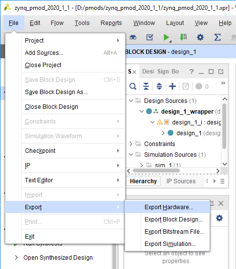
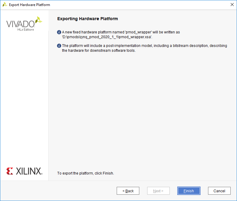
To export the hardware design, click Export → Export Hardware in the File menu.
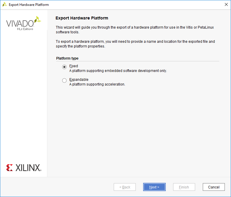
The wizard that pops up guides you through the options available for hardware export. The first screen allows you to select a Fixed or Expandable platform. In this case, choose a Fixed platform and click Next to continue.
This screen is not present in Vivado 2022.1, proceed to the next
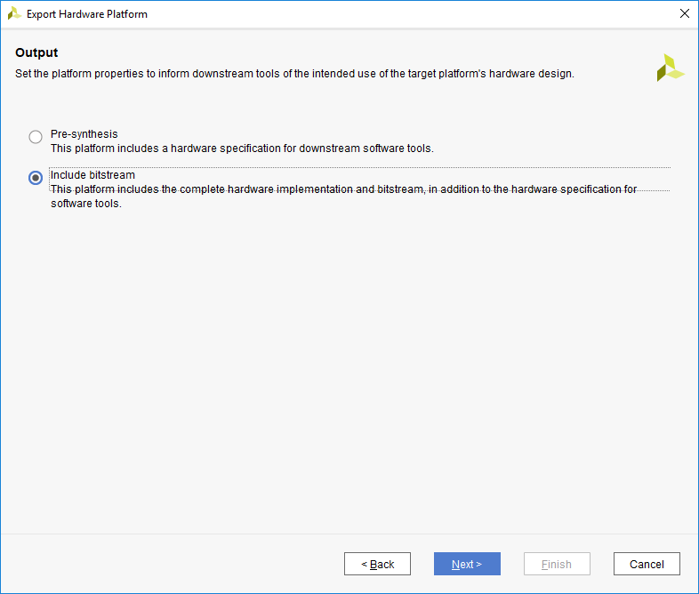
The Output screen allows you to select whether only the hardware specification (Pre-synthesis) should be exported, or whether the bitstream should be included. Since the bitstream has already been generated, it should be included in the platform so that Vitis can automatically figure out where it is when programming a board. Select Include bitstream and click Next to continue.
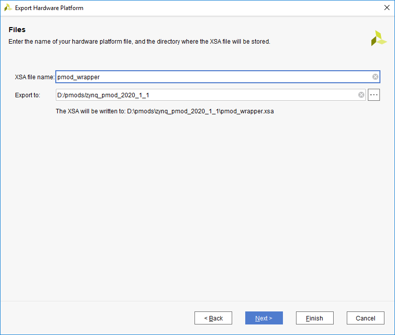
The Files screen gives you the option to choose a name for the Xilinx Shell Architecture (XSA) file, and provide a path to a folder that the file will be placed within. Give your XSA file a name, and choose a memorable location to place it in. This file will later be imported into Vitis, so take a note of where it is placed and what it is called.
Important: Do not use spaces in the file name or export path. Underscores or camelCase are recommended instead.
Click Next to continue.
The final screen of the wizard summarizes the options you selected. Click Finish.
- Update a Hardware Platform in Vitis
-
If a hardware design is changed after having created a Vitis application project, several steps must be taken in order to update the Vitis workspace with a newly exported XSA file. The XSA file contains all of the information relevant to Vitis about the hardware platform, and changing a platform project's specification based on this file will automatically load in any changes. This includes adding new drivers for new IP that have been installed and changing the files that define the addresses and other details of any installed IP that may have been renamed or had their addresses changed.
These steps assume that you have already regenerated the bitstream and reexported hardware in the same way that would be done prior to creating a new Vitis workspace.
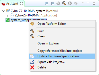
Within Vitis' Assistant pane, find the platform project that you wish to update with the new hardware. This project will typically have a name that ends with “_wrapper”, and is marked with the text “[Platform]”.
Right click on this project and select Update Hardware Specification.
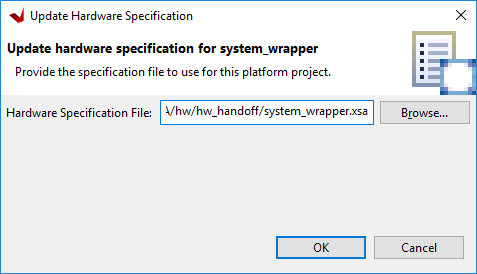
In the dialog that pops up, click Browse, and navigate to the location of the XSA file that you want the platform to target. Click Open to select this file.

Double check that the Hardware Specification File path matches that of the XSA file you want to use, then click OK to start the automatic process of updating the platform.
When complete, a dialog will pop up to state that the platform project has been updated. Click OK to acknowledge this.
At this point, changes to the hardware specification have been loaded into the hardware platform. The bitstream will have been updated, if it was loaded into the XSA file. The set of drivers and the xparameters file will have changed to match what is in the modified design. Changes to the software application may be required before the application can be built and programmed onto the board, however, detailing what may need to be done is outside of the scope of this guide.


Additional Resources
All materials related to the use of the name the primary product here can be found on its Resource Center.
All materials related to the use of the list other products here can be found on their resource centers, linked below:
For a walkthrough of the process of creating a simple baremetal software project in Vivado and Vitis, see Getting Started with Vivado and Vitis for Baremetal Software Projects. Information on important parts of the GUIs, and indirect discussion of the steps required to modify, rebuild, and run this demo in hardware can also be found here.
For technical support, please visit the FPGA section of the Digilent Forum.
Some board resource centers use tags to automatically pull their demos into lists. In these cases, the tag syntax in the code block below should be used. Do NOT remove the code block until the page has been finalized, or else it will be pulled automatically into various resource centers.
{{tag>project zybo-z7}}