Unit 7: Audio Signal Processing
Unit 7 Labs
Download This Document
1. Introduction
This unit focuses on processing signals in the audio frequency range using digital signal processing (DSP) concepts with the PIC32MX370 microprocessor. Lab 7a investigates a method of generating multiple frequency signals without using transcendental functions or lookup tables. Lab 7b uses Discrete Fourier Transforms (DFT) to detect the presence of signals. It is not the purpose of this unit to teach the theory of digital filtering, but rather to teach how to implement digital filtering using a conventional microprocessor in lieu of specialized digital signal processors.
2. Objectives
- Extend the applications of digital signal processing introduced in Unit 6.
- Use a DSP algorithm to synthesize sine waves.
- Use a DSP algorithm to analyze a periodic signal using Discrete Fourier Transforms.
- How to implement DSP algorithms on the PIC32 processor using C.
- How to use the PIC32 MIPS DSP library to increase the DSP algorithm execution speed.
3. Basic Knowledge
- Interfacing with an LCD
4. Equipment List
4.1. Hardware
- Workstation computer running Windows 10 or higher, MAC OS, or Linux
In addition, we suggest the following instruments:
4.2. Software
The following programs must be installed on your development workstation:
- WaveForms (if using the Analog Discovery 2)
- Iowa Hills Software for IIR and FIR Filters (used for illustrative purposes and is not required)
5. Project Takeaways
- How to implement digital filters in C using a PIC32 microprocessor.
- How to create analog output using pulse-width modulation.
- How to sample an analog input at a specified rate.
- How to use the PIC32 processor to make a signal generator.
- How to use the PIC32 processor to make a real-time frequency spectrum analyzer.
6. Fundamental Concepts
6.1. Signal Processing
As introduced in Unit 6, signal processing is an enabling technology that encompasses the fundamental theory, applications, algorithms, and implementations of processing and transferring information. This information is contained in many different physical, symbolic, or abstract formats broadly designated as signals. In this unit, we will employ both analog and digital signal processing. Analog signal processing will be used to implement frequency filters for both microprocessor inputs and outputs. The analog filters are electronic circuits operating on continuous-time analog signals. Digital filters use computers and microprocessors to perform mathematical operations on sampled, discrete-time signals to reduce or enhance certain aspects of that signal. We looked at how both analog and digital filters are used in open and closed-loop digital control in Labs 6a and 6b. It became apparent that the timing for sampling the inputs and generating the output must occur at fixed intervals.
6.2. Analog Signal Processing
Analog signal processing is any type of signal processing conducted on continuous analog signals by some analog means. This usually involves electronic circuits consisting of resistors, capacitors, inductors, and high gain differential amplifiers. The term “analog” refers to signals or information that is continuously variable. Mathematically, this implies that the signal can be differentiated an infinite number of times.
Electronic analog computers are able to process analog signals using electronic operational amplifiers to implement the basic mathematical operations such as add, subtract, multiply, and divide transcendental functions such a logarithms and exponentials, as well as integral and differential calculus. Programming analog computers is tantamount to wiring electronic circuits, making them difficult to construct and modify. Although analog computers have been replaced by microprocessors, they are frequently used to implement electronic filters for signal conditioning of digital computer inputs and outputs. Analog filters have the advantage of being able to operate at higher power levels and frequencies.
6.3. Digital Signal Processing
Digital signal processing (DSP) is the use of digital computers to implement digital processing to perform a wide variety of signal processing operations. The signals processed in this manner are a sequence of numbers that represent samples of a continuous variable in a domain such as time, space, or frequency.
Digital computers, particularly in the form of microprocessors, have replaced the computing effort that was formerly allocated to many analog computers. Digital computers cannot directly process analog input signals without first converting the signal into representations of the signal as discretely varying levels using an analog-to-digital converter (ADC). Digital computers can generate discretely varying output using a digital-to-analog converter (DAC), but to get truly continuous output, the DAC output must be further filtered using an analog filter.
The following discussions provide an outline of the process of designing digital filters. The reader who is interested in an extensive discussion of the field of digital signal processing is directed to Reference 6 that is a PDF book by Steven Smith.
6.3.1. Digital Filters
A digital filter is a system that performs mathematical operations on a sampled, discrete-time signal to reduce or enhance certain aspects of that signal. Unit 6, along with Lab 6b, introduces DSP as applies to digital control. In Unit 7, we will apply digital filters to generate and analyze analog signals as modeled in the block diagram in Fig. 6.1.
 Figure 6.1. Block diagram of a digital filter implemented using a microprocessor.
The DSP algorithm repeatedly processes inputs and generates new outputs at a constant rate. This requires sampling and converting the filtered analog input signal at this same rate or a multiple of it. Although the maximum rate that the final DAC analog output can be generated at is the processing rate, outputs can be delayed or generated at lower rates. Unless specifically required, most digital filtering systems sample inputs, process data, and generate output at the same rate. Any variation of the processing rate results in generating incorrect outputs.
Many digital filters are based on design processes utilizing parameters that specify frequency responses in the continuous domain, as expressed with rational polynomials as a function of the Laplace operator “s”. The general form of this polynomial is shown in Eq. 6.1. The study of digital filtering covers the methodologies for determining the specific values for the filter constants $b_j$ and $a_i$ based on the filter criteria.
$$\frac{Y(s)}{X(s)} = H(s) = \frac{\sum_{j=0}^{M-1}b_j \cdots^j}{\sum_{i=0}^{N-1}a_i \cdot s^i} \qquad (\text{Eq. 6.1})$$
Where $Y(s)$ is the system output and $X(s)$ is the system input.
Once the transfer function has been determined that meets the required filter frequency response, the continuous domain transfer function must be approximated by a digital domain transfer function that digital computers can implement as algorithms using programming code. One of the popular approximations is called the bilinear transformation and is expressed by Eq. 6.2.
$$s = \frac{2}{Ts} \frac{1-z^{-1}}{1+z^{-1}} \qquad (\text{Eq. 6.2})$$
Where $Ts$ is the sampling period.
The result of the substitution of Eq. 6.2 into Eq. 6.1 is also a rational polynomial, as shown in Eq. 6.3, that relates the output, $Y(z)$, to the input, $X(z)$. The polynomial coefficients $d_j$ and $c_i$ are not the same values as $b_j$ and $a_i$ used in Eq. 6.1.
$$H(z) = \frac{y(z)}{X(z)} = \frac{FILTERGAIN \cdot \sum_{j-0}^{M-1} d_j \cdot z^{-1}}{1 + \sum_{i=1}^{N-1} c_j \cdot z^{-i}} = \frac{FILTERGAIN \cdot \sum_{j=0}^{M-1} d_j \cdot X(z) \cdot z^{-j}}{1 + \sum_{i=1}^{N-1} c_i \cdot Y(z) \cdot z^{-i}} \qquad (\text{Eq. 6.3})$$
Solving Eq. 6.3 for the output, $Y(z)$, as a function of the input, $X(z)$, results in Eq. 6.4.
$$Y(z) \cdot \bigg[ 1+ \sum_{i=1}^{N-1} c_i \cdot z^{-i} \bigg] = FILTERGAIN \cdot X(z) \cdot \bigg[ \sum_{j=0}^{M-1} d_j \cdot z^{-j} \bigg] \qquad (\text{Eq. 6.4})$$
Using the relationship that the inverse $z$ operator is a delay of one sample, $X(z) \cdot z^{-i}$ becomes $x(n-i)$. Hence, Eq. 6.5 is the inverse $z$ transform of Eq. 6.3.
$$y(n) + \sum_{i=1}^{N-1} c_i \cdot y(n-i) = FILTERGAIN \cdot \sum_{j=0}^{M-1} d_j \cdot x(n-j) \qquad (\text{Eq. 6.5})$$
Here the nth term is the present input or most recent sample. The $(n-i)^{th}$ and $(n-j)^{th}$ terms are past outputs and inputs, respectively. Eq. 6.6 represents an equation that can be solved on a computer. This form of a digital filter is called an infinite impulse response filter because it involves past outputs in the computation. Listing A.3 in Appendix A is a C function that can implement a fourth order IIR filter.
$$y(n) = FILTERGAIN \cdot [b_0 \cdot x(n) + b_1 \cdot x(n-1) + b_2 \cdot x(n-2) + b_3 \cdot x(n-2)] - [a_1 \cdot y(n-1) + a_2 \cdot y(n-2) + a_3 \cdot y(n-3) + a_4 \cdot y(n-4)] \qquad (\text{Eq. 6.6})$$
As will be shown below, the implementation of a digital filter is not complicated. The real science of designing digital filters lies in the selection of the design parameters that eventually produce the polynomial coefficients $b_j$ and $a_i$. While Reference 6 and 7 provide the theoretical basis for digital filter design, much of the technical background can be minimized by using filter design software programs such as the one provided by Reference 8.
6.3.1. FIR C Program
Finite impulse response (FIR) filters are a class of digital filters that only use present and past inputs. FIR filters can be expressed by Eq. 6.5 where all ci coefficients are zero, thus resulting in Eq. 6.7. FIR filters have a finite response to any input.
$$y(n) = FILTERGAIN \cdot \sum_{j=0}^{M-1} d_j \cdot x(n-j) \qquad (\text{Eq. 6.7})$$
Since FIR filters do not use any feedback, any rounding errors are not compounded by summed iterations, resulting in the same relative error in each consecutive calculation. FIR filters are inherently stable since the output is the sum of a finite number of finite multiples of the input values. Therefore, the output can be no greater than times the largest value appearing in the input. FIR filters can be designed to have linear phase by making the coefficient sequence symmetric. This property is sometimes desired for phase-sensitive applications, e.g. data communications, seismology, and crossover filters.
The main disadvantage of FIR filters is that considerably more computation power in a general purpose processor is required compared to an IIR filter with similar sharpness or selectivity, especially when low frequency (relative to the sample rate) cutoffs are required. However, many digital signal processors provide specialized hardware features to make FIR filters approximately as efficient as IIR for many applications.
Figure 6.2 is a screenshot of a FIR design for a low-pass filter with 2.0 kHz and 3db cutoff frequency. This was done using Iowa Hills Filter Design Software. A few comments are in order to explain the process of entering the filter specifications into the Iowa Hills filter designer. The entry box labeled OmegaC is the place where the filter 3db cutoff frequency is set. The filter specification for this example of a 16 tap FIR filter has a cutoff frequency of 2 kHz and a sampling frequency of 16 kHz. The normalized cutoff radian frequency, ωc, must first be converted to a ratio of the cutoff frequency, Fc, to the sampling frequency, Fs, as shown in Eq. 6.8. Eq. 6.9 pre-warps the cutoff frequency to compensate for frequency distortion generated by the bilinear transformation. Hence, the entry for OmegaC shown in Fig. 6.2 uses a cutoff frequency of 2111 Hz for the analog filter design algorithm so that the resulting digital filter will have a cutoff frequency of 2000 Hz.1) The coefficients shown on the right side of Fig. 6.2 are for a 16 tap FIR filter using the raised cosine prototype. Applying window functions reduces the main lobe roll-off rate but has the benefit of reducing the amplitude of the first side lobe.
$$\omega c = 2\pi FcFs \qquad (\text{Eq. 6.8})$$
$$OmegaC = 2\pi \cdot \tan (\frac{\omega c}{2}) \qquad (\text{Eq. 6.9})$$
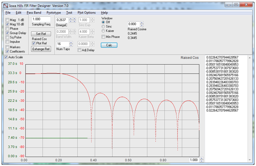 Figure 6.2. 16 Tap FIR Filter response and design coefficients.
Listing A.2 is the C code for the FIR digital filter using Q1.15 fixed point math. The Q1.15 fixed math scaled filter coefficients are generated by multiplying the coefficients listed on the right-hand window of Fig. 6.2 by 215. The code shown for fir_C_filter initially saves past inputs before implementing the algorithm using Eq. 6.7. Listing A.1 shows the code to implement the FIR filter using the MIPS DSP library function. The function setup_fir_filter is called during initialization while the function fir_MIPS_filter is called each time a new input data sample is processed. The fir_MIPS_filter function executes the FIR filter almost 7 times faster than the fir_C_filter function.
6.3.2 IIR C Program
Infinite impulse response (IIR) filters, or recursive filters, are a class of digital filters that only use present and past inputs and past outputs. Mathematically, the IIR filter algorithm is expressed by Eq. 6.4. They are called infinite impulse response because, in theory, an input - even an impulse - has infinite influence on the filter output.
The main advantage digital IIR filters have over FIR filters is their efficiency of design specifications in terms of filter prototype, bandwidth, cutoff frequency, ripple, and/or roll-off. Such a set of specifications can be met with a lower order IIR filter than would be required for an FIR filter meeting the same requirements. When implemented in a signal processor, this implies a correspondingly fewer number of calculations per time step. The computational savings is often a rather large factor.
IIR filters with linear phase (constant group delay vs frequency) are difficult to design. Digital IIR filters are susceptible to limit cycle behavior when idle, due to the feedback system in conjunction with quantization. Coefficient quantization can also result in an unstable filter.
Figure 6.3 is a screenshot of an IIR design for a low pass filter with 2.0 kHz and 3db cutoff. The same consideration for the parameter $OmegaC$ discussed in section 6.3.1 above apply here as well. The coefficients on the right are for different implementation algorithms. The $N^{th}$ order coefficients are used for implementing the algorithm shown in Eq. 6.5 and Eq. 6.6. Note that the magnitudes of the denominator coefficients are greater than unity, hence there will be an overflow if we attempt to use the Q1.15 format. However, if both the numerator and denominator coefficients are divided by two after the Q1.15 scaling, all coefficients will be less than unity and the filter will retain the desired characteristics. Halving the filter coefficients after Q1.15 scaling is the same as scaling by Q2.14. The C code for the IIR filter using these coefficients is shown in Listing A.4.
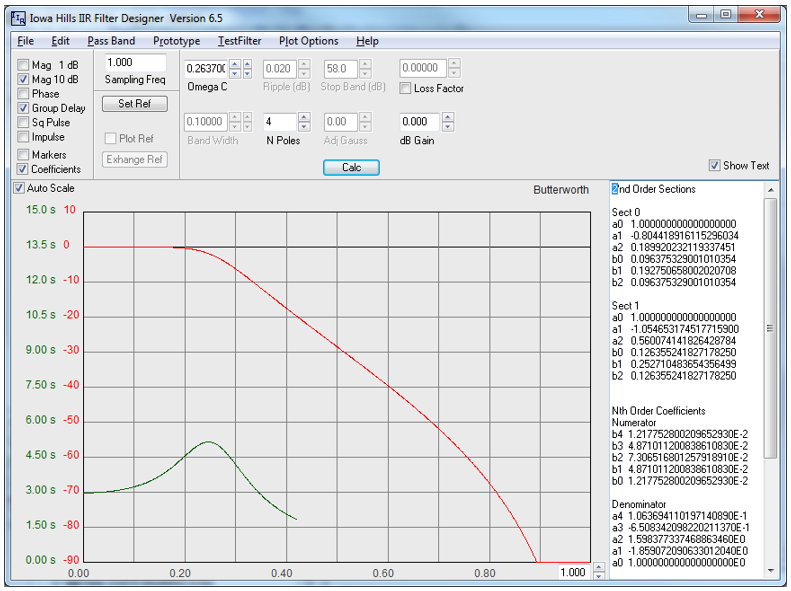 Figure 6.3. 4th order IIR Butterworth filter response and design coefficients.
The second set of coefficients shown in Fig. 6.3 is used for a biquadratic implementation of an IIR filter. Each stage can be modeled as shown in Fig. 6.4. Multistage biquadratic filters are cascaded together to implement filters of order greater than two. As noted from Fig. 6.3, the denominator has coefficients with magnitudes greater than unity, hence we will use Q2.14 format. A fourth order IIR filter requires two second order biquadratic IIR filters. Listing A.3 is an example of using the MIPS library functions for implementing a IIR filter. The function, setup_iir_filter, is called in the system initialization. The function iir_filter is called to process each new data sample.
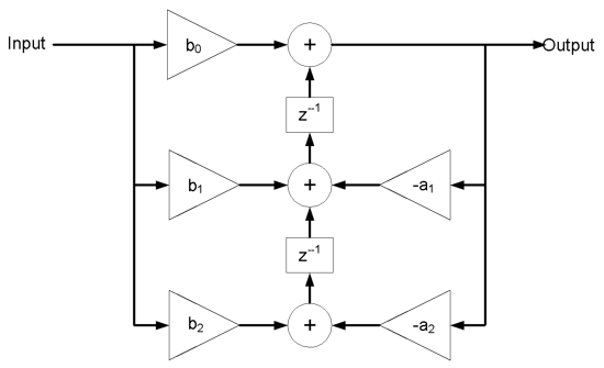 Figure 6.4. Flow diagram of a single stage bi-quadratic IIR digital filter.
Figure 6.5 is a diagram of a single stage biquadratic IIR filter used by the MIPS DSP library. This unconventional model shows that there is no implementation of the $B_0$ or $A_0$ terms. Section 2.1.1.1 of the application note cited by Reference 10 explains how to convert the biquadratic coefficients shown in Fig. 6.4 to the coefficients shown in Fig. 6.5. The conversion is outlined by Eq. 6.10 through 6.12.
$$A_{i,j} = -a_{i,j} \cdot 2^{13}, i \text{and} j = 1,2 \qquad (\text{Eq. 6.10})$$
$$B_i = \bigg( \frac{b_{i,j}}{b_{0,j}} \cdot 2^{13}, i \text{and} j = 1,2 \qquad (\text{Eq.6.11})$$
$$scale = \sqrt{max \big( log_2(b1_0 \cdot b2_0) \big)} \qquad (\text{Eq. 6.12})$$
Since the scale factor is always less than or equal to 2 raised the product of b10 and b20, the gain of the filter will be less than or equal to unity. The code shown in Listing A.3 shows that the compensating gain for the example IIR filter is 2.51. Performance tests show that the IIR filter implemented using the MIP DSP library function is almost 15 times faster than using only C statements.
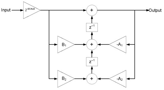 Figure 6.5. Flow diagram of a single stage MIPS IIR Biquadratic filter.
Figure 6.6 plots the response of the four filter algorithms for Listing A.1 through A.4. Only three plots are distinguishable because the results of the input X and the IIR1 corresponding to Listing A.1, as well as the FIR filter result for FIR1 are nearly identical.
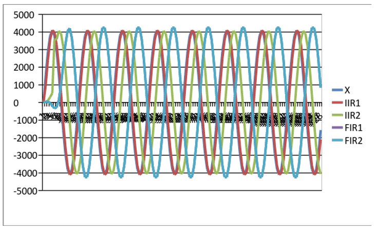 Figure 6.6. Plot of outputs of the four example filters to a 1 kHz input sine wave.
7. Lab Exercises
As modeled in Fig. 7.1, the blocks shaded blue represent analog circuits and components. The blocks shaded green represent the hardware resources within the microprocessor itself. The electromechanical transducers are the speaker in Fig. 7.1 and the microphone in Fig. 7.2.
Figure 7.1 is the block diagram for Lab 7a that implements a sine wave generator using an IIR filter. The frequency of the synthesized sine wave is selected by setting one of the eight slide switches on the Basys MX3 board high. The frequencies synthesized range from 500 to 7500 Hz in steps of 1000 Hz. Refer to Lab 7a for details concerning the algorithms to synthesize a sine wave and project specifications. The Basys MX3 board LCD will display the selected frequency and the on-board amplifier-speaker circuit shown in Fig. B.1 of Appendix B.
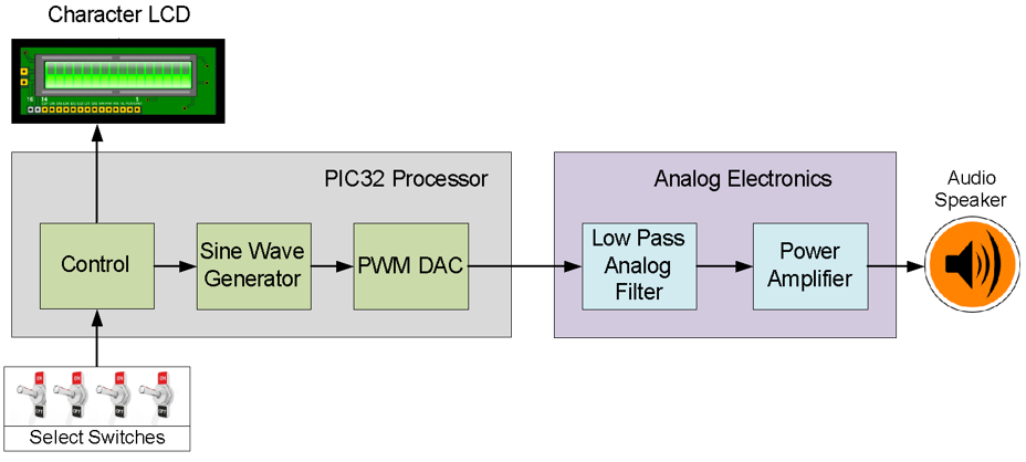 Figure 7.1. Block diagram of a digital signal generator (Lab 7a).
Figure 7.2 is the block diagram for Lab 7b that implements a frequency spectrum analyzer using discrete Fourier transforms (DFT) implemented by an FIR type algorithm. One DFT algorithm will be programmed using conventional C statements while a second DFT algorithm will use a MIPS DSP library function. The Basys MX3 board LCD will input the audio signal using the Basys MX3 microphone circuit, shown in Fig. B.2, and will display the frequency spectrum on the on-board LCD.
 Figure 7.2. Block diagram of a digital spectrum analyzer (Lab 7b).
8. References
- Basys MX3 Trainer Board Reference Manual
- PIC32 Family Reference Manual, Timers Section 14: http://ww1.microchip.com/downloads/en/DeviceDoc/61105E.pdf
- Steven W. Smith, The Scientist and Engineer’s Guide to Digital Signal Processing, http://www.dspguide.com/pdfbook.htm
- “Design of Digital Filters”, https://web.eecs.umich.edu/~fessler/course/451/l/pdf/c8.pdf
- Iowa Hills Software Digital and Analog Filters, http://iowahills.com/
- “A Discrete Fourier Transform Based Digital DTMF Detection Algorithm”, http://www.rootsecure.net/content/downloads/pdf/paper_dtmf.pdf
- Application Report SPRA867, “Parametric Equalization on TMS320C6000 DSP”, http://www.ti.com/lit/an/spra867/spra867.pdf
Appendix A: Filter C Code
Listing A.1. C Code to Implement a 16 tap FIR Digital Filter Using MIPS FIR Function
#define K 16
int16_t delayline[K] = {0};
int16_t coeffs2x[2*K] = {0};

void setup_fir_filter(void)
{
int i;
   for (i = 0; i < K; i++)
        delayline[i] = 0;
// lowpass2KHzFIRCoefs declared in Listing 3
   mips_fir16_setup(coeffs2x, lowpass2KHzFIRCoefs, K);

}

int16_t fir_MIPS_filter(int16_t indata)
{
int i;
int15_t outdata;

   mips_fir16(&outdata, &indata, coeffs2x, delayline, 1, K, 0);

   return outdata;
}
Listing A.2. C Code to Implement a 16 tap FIR Digital Filter Using Fixed Point Math
int16_t lowpass2KHzFIRCoefs[16]=
{
   (int16_t) ( 0.022642707844628567 * Q15),
   (int16_t) (-0.011786057779962828 * Q15),
   (int16_t) (-0.050116510848049953 * Q15),
   (int16_t) (-0.057537731307973683 * Q15),
   (int16_t) (-0.008530151801383020 * Q15),
   (int16_t) ( 0.092467681565975166 * Q15),
   (int16_t) ( 0.207569427201626133 * Q15),
   (int16_t) ( 0.283948226483300703 * Q15),
   (int16_t) ( 0.283948226483300703 * Q15),
   (int16_t) ( 0.207569427201626133 * Q15),
   (int16_t) ( 0.092467681565975166 * Q15),
   (int16_t) (-0.008530151801383020 * Q15),
   (int16_t) (-0.057537731307973683 * Q15),
   (int16_t) (-0.050116510848049953 * Q15),
   (int16_t) (-0.011786057779962828 * Q15),
   (int16_t) ( 0.022642707844628567 * Q15)
};

int fir_C_filter(int indata)
{
#define FIR_ORDER 16		// Filter order
/*
   Fixed point math uses Q1.15 format to scale coefficients
*/
static int x[FIR_ORDER] = {0};	// Input memory array initialized to zero
static int y[FIR_ORDER] = {0};	// Output memory array initialized to zero
int i,j;
   for(j = FIR_ORDER; j > 0; j--) // Time shift past inputs and outputs
   {
       x[j] = x[j-1];
       y[j] = y[j-1];
   }
   x[0] = indata;
   y[0] = (x[0] * lowpass2KHzFIRCoefs[0]);
   for(j = 1; j < FIR_ORDER; j++)
   {
       y[0] += (x[j] * lowpass2KHzFIRCoefs[j]);
   }
   y[0] /= Q15;			// Normalize the result
   return y[0];
}
Listing A.3. C Code to Implement a Fourth Order IIR Digital Filter Using MIPS IIR Function
#define B	2

biquad16 bq[B];
int16_t coeffs[4*B];
int16_t delayline[2*B];

void setup_iir_filter (void)
{
int i;
//initialize delayline iir filter with zero
   for (i = 0; i < 2*B; i++)
       delayline[i] = 0;

   bq [0].a1 = 6590;   //a( 1,1)/2
   bq [0].a2 = -1556;  //a( 1,2)/2
   bq [0].b1 = 2048;   //b( 1,1)/2
   bq [0].b2 = 1024;   //b( 1,2)/2

   bq [1].a1 = 8640;   //a( 2,1)/2
   bq [1].a2 = -4588;  //a( 2,2)/2
   bq [1].b1 = 2048;   //b( 2,1)/2
   bq [1].b2 = 1024;   //b( 2,2)/2

   mips_iir16_setup(coeffs, bq, B);
}

int16_t iir_filter (int16_t indata)
{
int i;
int16_t outdata;
int gain = 2.51;

//calculate iir filter biquad
   outdata = mips_iir16(indata, coeffs, delayline, B, 1);
   return outdata * gain;
}
Listing A.4. C Code to Implement a Fourth Order IIR Digital Filter Using Fixed Point Math
int iir_filter(void)
{
#define IIR_ORDER 4	// Filter order
/*
Constants b0 – b3 and a1 – a3 as well as FILTERGAIN are defined as Q1.13 scaled signed integer 16 data types.

*/
#define Q14	1<<14			// Scale factor
static int x[IIR_ORDER] = {0};	// Past input memory array initialized to zero
static int y[IIR_ORDER] = {0}; 	// Past output memory array initialized to zero
int i;

// propagate past inputs and outputs
   for(i = ORDER; i > 0; i--)
   {
       x[i] = x[i-1];
       y[i] = y[i-1];
   }
   x[0] = sample;			// Save the newest input value
   y[0] = x[0] * b0;		// Compute the first numerator term

// Compute the remaining filter terms
   for(i = 1; i < ORDER; i++)
   {

       y[0] += ((x[i] * b[i]) * FILTER_GAIN) - (y[i] * a[i]);
   }
   y[0] /= Q14;			// Normalize the result
   return ( y[0] ); 		// Return the filter output */
}
Appendix B: Audio Amplifiers
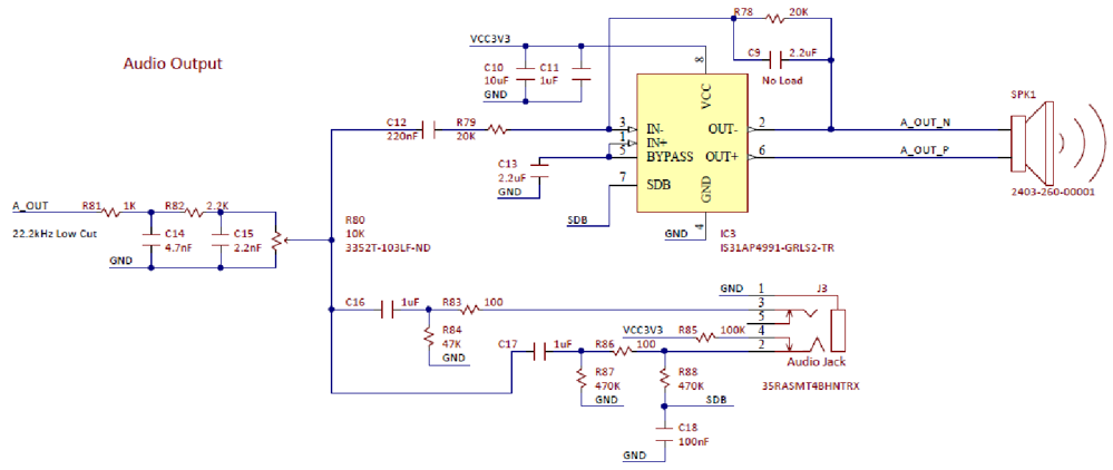 Figure B.1. Basys MX3 Trainer Board Audio Output Schematic Diagram.
 Figure B.2. Basys MX3 Microphone Schematic.
