Compensating BNC Oscilloscope Probes

Overview

BNC oscilloscope probes are commonly used for analog inputs on many oscilloscopes, offering both the ability to read higher voltages than an oscilloscope natively supports as well as higher bandwidth, providing users better insight into the high-speed signals they are observing with much more accuracy than what is offered by MTE cables. However, as the 10x mode of the BNC probe adds extra resistance to correspondingly attenuate the input signal down by a factor of 10, the capacitance of the BNC probe is not likely to match the capacitance of the analog input channel you are using, resulting in the measured signal to be over- or under-compensated rather than accurately showing the signal you are viewing. Luckily, this can be mitigated by adjusting the capacitance of the BNC probe.

This guide walks through how to make this adjustment for Digilent's Test and Measurement devices.


Inventory

  • A BNC probe to be compensated
    • This guide will use the BNC probes kitted and included with Digilent's various T&M devices.
  • An oscilloscope with a BNC connectors:
  • A square wave source:
    • Analog Discovery Pro (ADP5250) features dedicated Probe Compensation tabs
    • For other devices, the built-in Arbitrary Waveform Generator can be used to produce 5 kHz square waves
      • An example WaveForms workspace to compensate a BNC probe on Scope Channel 1 is available for download here.
  • A flathead screwdriver to adjust the compensation trimmer on the BNC probe
    • A small plastic screwdriver is typically included with BNC probe packs.

Guide

This guide is broken up into sections for each type of device that might require probe compensation. Open the dropdown corresponding to your device to view the required steps.

Hardware Setup

Analog Discovery Pro 2000 Series (ADP2230)

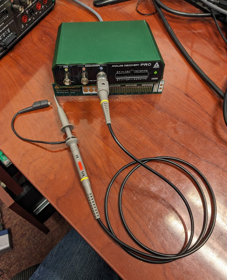
Connect the probe that is to be compensated to the desired BNC input channel of the oscilloscope and set the probe to its 10x attenuation setting.

Note that the BNC probe is connected in such a way to provide easy access to the compensation trimmer.

The PCB ruler is there to hold up the ADP2230 for photo purposes.
Figure 20: Connect the BNC probe to the preferred oscilloscope channel and slide the switch to the 10x attenuation setting.

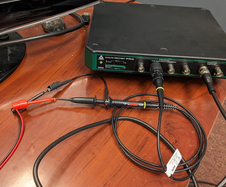
If using one of the Analog Discovery Pro 3000 series with no other source of a square wave, attach a BNC minigrabber (or similar) to a Wavegen output and connect the positive end to the probe tip and the ground end to the probe ground clip.

It is recommended to use BNC to minigrabber cables instead of BNC Probes on the analog output BNC port to avoid any bandwidth limitations on 1x mode or corresponding signal attenuation on 10x mode.

The PCB ruler is there to hold up the ADP2230 for photo purposes.
Figure 21: Connect the BNC probe ground clip to AWG ground clip and the BNC probe tip to the AWG output.

Analog Discovery Pro 3000 Series (ADP3450/ADP3250)

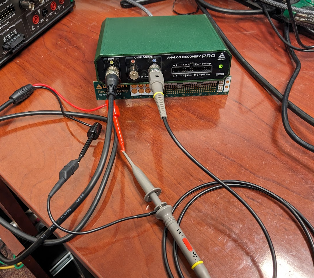
Connect the probe that is to be compensated to the desired BNC input channel of the oscilloscope and set the probe to its 10x attenuation setting.

Note that the BNC probe is connected in such a way to provide easy access to the compensation trimmer.

Scope channel 2 is used in this photo, but connect the probe to whatever channel you plan on using.
Figure 22: Connect the BNC probe to the preferred oscilloscope channel and slide the switch to the 10x attenuation setting.

If using one of the Analog Discovery Pro 3000 series with no other source of a square wave, attach a BNC minigrabber (or similar) to a Wavegen output and connect the positive end to the probe tip and the ground end to the probe ground clip.

It is recommended to use BNC to minigrabber cables instead of BNC Probes on the analog output BNC port to avoid any bandwidth limitations on 1x mode or corresponding signal attenuation on 10x mode.

Connect the BNC probe to the BNC minigrabber.
Figure 23: Connect the BNC probe ground clip to AWG ground clip and the BNC probe tip to the AWG output.

Analog Discovery Pro 5000 Series (ADP5250)

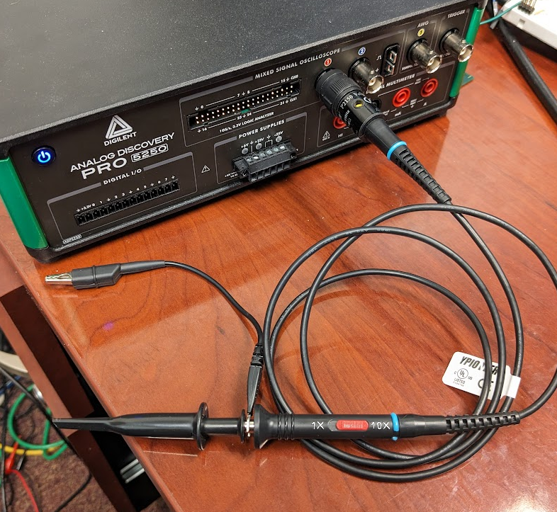
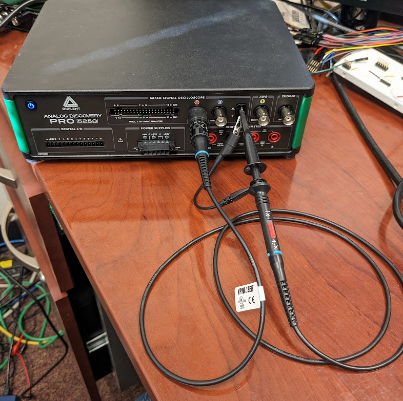
Connect the probe that is to be compensated to the desired BNC input channel of the oscilloscope and set the probe to its 10x attenuation setting.

Note that the BNC probe is connected in such a way to provide easy access to the compensation trimmer.

Connect the BNC Probe to the oscilloscope channel you wish to compensate for.
Figure 24: Connect the BNC probe to the preferred oscilloscope channel and slide the switch to the 10x attenuation setting.

Connect the probe tip to the top tab in the compensation box with the square wave symbol, and the probe ground clip to the lower connector with the ground symbol.

The compensation tabs directly on the device provide a constant square wave.
Figure 25: Connect the BNC probe to the compensation tabs that are provided on the device.

Analog Discovery 3 or Analog Discovery 2 with BNC Adapter

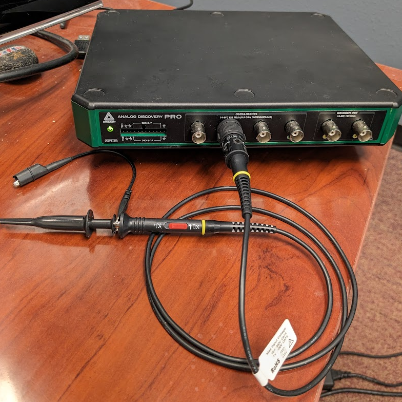
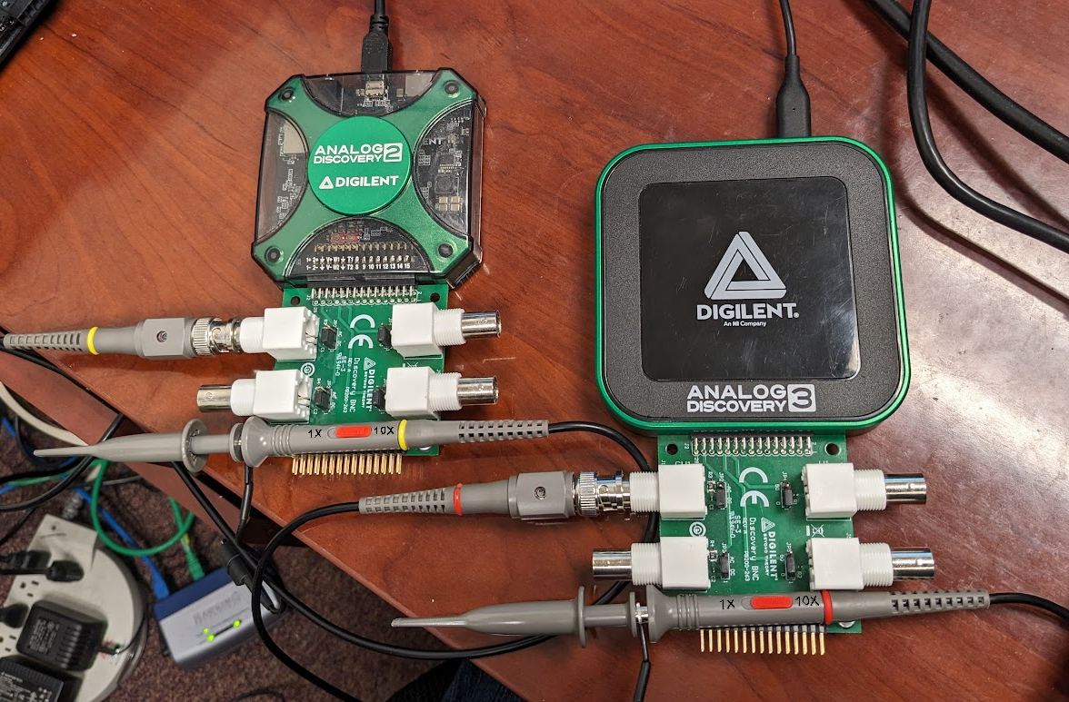
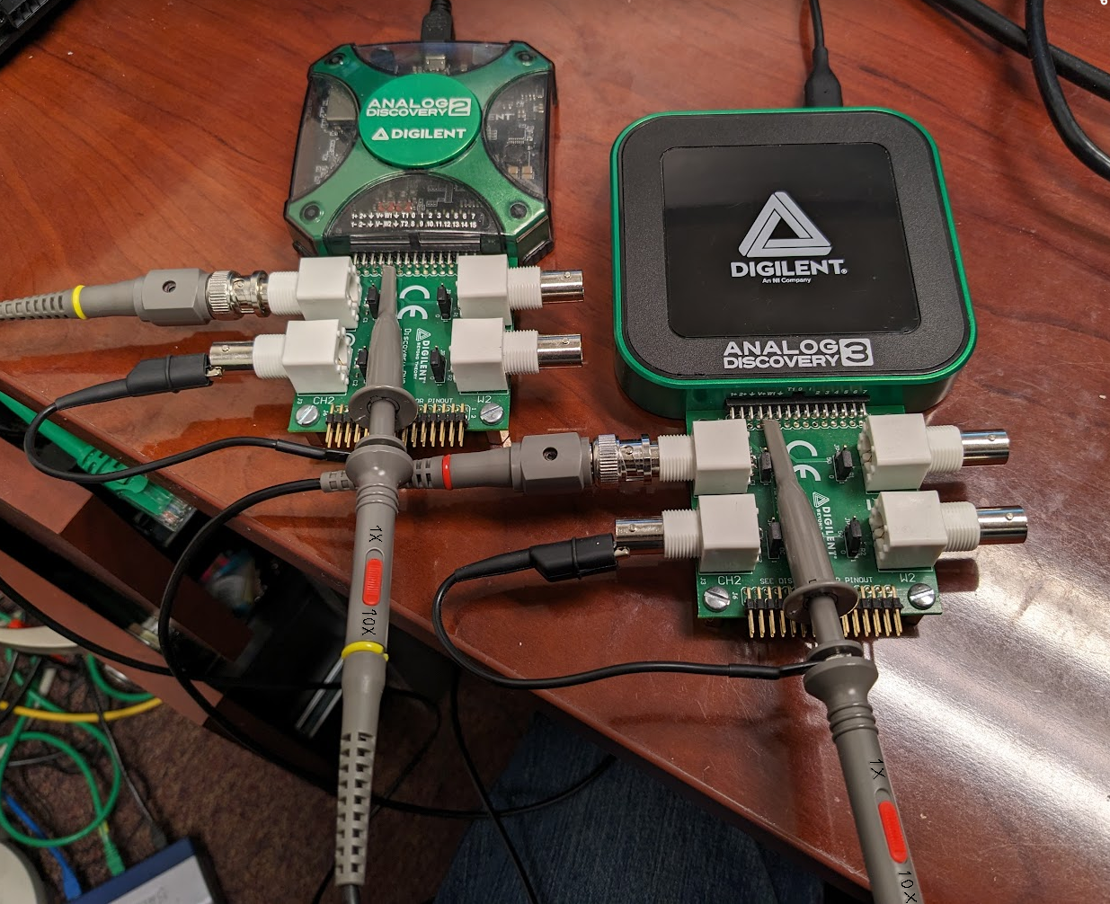
Connect the probe that is to be compensated to the desired BNC input connector on the BNC Adapter that is associated with the oscilloscope channel you wish to compensate for and set the probe to its 10x attenuation setting.

Note that the BNC probe is connected in such a way to provide easy access to the compensation trimmer.

The AD3 in the photo is a prototype, hence the different coloring on the plastic shell.
Figure 26: Connect the BNC probe to the preferred oscilloscope channel and slide the switch to the 10x attenuation setting.

Connect the probe ground clip to the metal of one of the outside BNC connectors as that is tied to the system ground, and connect the probe tip to the right angle pin associated with Wavegen Channel 1 − this will be the “top” pin, 5th from the left, directly below the “W1” label.

Connect the BNC probe directly to the pin for the best signal clarity.
Figure 27: Connect the BNC probe directly to the Wavegen output and the ground clip to one of the BNC connector shells on the adapter.

WaveForms Setup

A reference workspace with the recommended setup is available for download in the Inventory. Instructions on how to recreate the workspace for yourself are provided below.

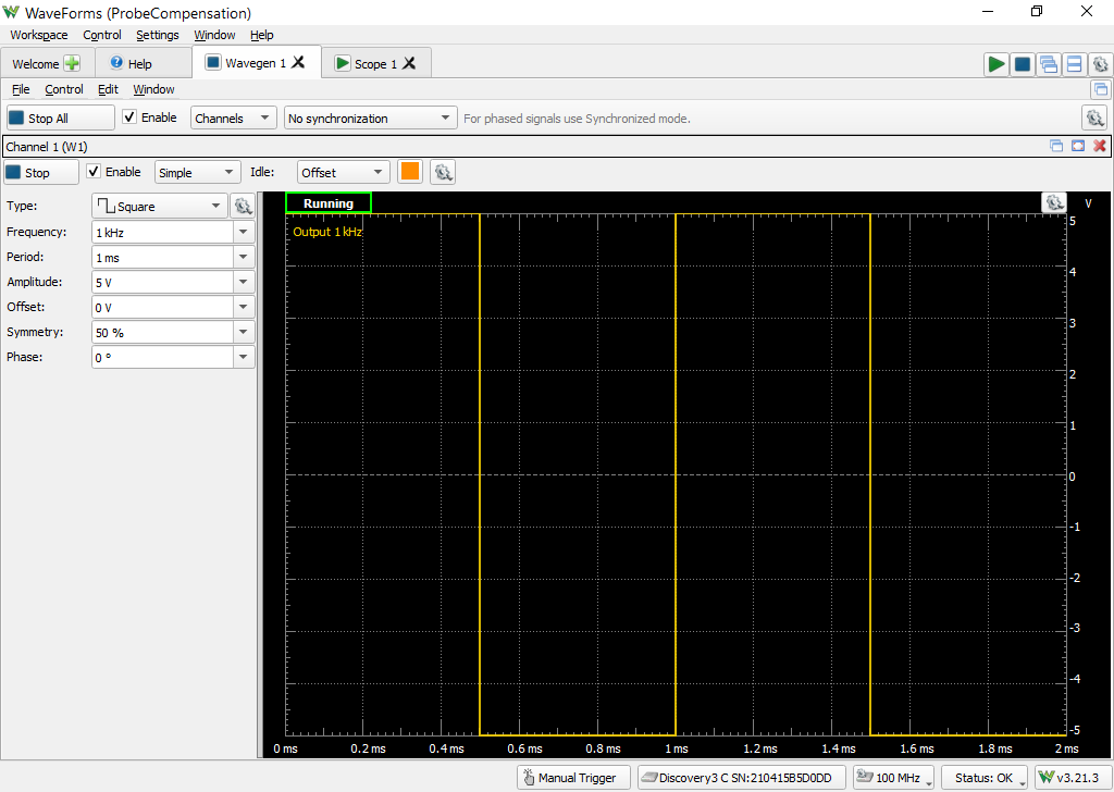
Open the Wavegen tool within WaveForms and configure the output on Wavegen Channel 1 to be a 1 kHz Square wave with an amplitude of 5 V.

Note: If using an ADP 5000 series device, this step is unneeded as you will be using the compensation tabs which automatically provide their own square wave of the appropriate settings.

A 5 V, 1 kHz square wave is created on Wavegen channel 1
Figure 28: A 5 V, 1 kHz square wave is created on Wavegen channel 1

Open the Scope tool in the WaveForms software. Enable the appropriate channel corresponding to what your probe is attached to (likely channel 1) and adjust the following settings:

  • Set the level of the rising edge trigger to be at 1 V.
  • Set the Time Base to 500 μs/div
  • Set the enabled channel voltage Range to 1.25 V/div. You can manually type in the box to set this value.
  • If not visible, click the gear icon associated with the oscilloscope channel and change the Probe attenuation to 10x to have WaveForms automatically adjust the rendered scaling of the received signal.
  • Uncheck any additional oscilloscope channels that you are not viewing for visual clarity.

Click the Run All green arrow in the upper right hand corner to start both the Scope and Wavegen instruments.

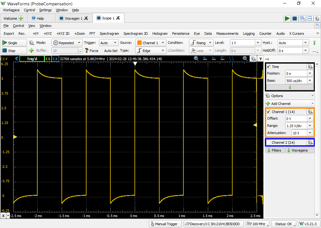
An example of an unattenuated signal that you might see is shown in Figure 29. Note that the provided square wave is in fact not “square” and instead has some overshoot.

What you might see when initially compensating your BNC probe.
Figure 29: An example of what an unattenuated square wave might look like.

Use a small flathead screwdriver (a small plastic one is typically included with BNC probes) to adjust your probe's compensation capacitor until the square wave visible in the Scope plot looks appropriately square. The probe trimmer is often located on the BNC connector end of the probe as shown in Figure 30.

A small video showing an example of adjusting an overcompensated probe to instead be a flat square wave can be found in Figure 31.
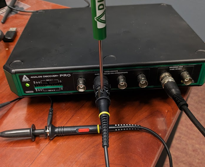
I unironically love this screwdriver. The phillips and flat head ends are actually useful sizes.
Figure 30: Use a flat head screwdriver to adjust the BNC probe trimmer.
Figure 31: A video showing an example of what you might see while compensating the BNC probe.

Next Steps

You have now successfully compensated your BNC probe to a particular oscilloscope channel by adjusting its capacitance to match the capacitance of the oscilloscope channel.

You can find more information about your Mixed-Signal Oscilloscope through its Resource Center, which can be found via the Test and Measurement page of this site.

Other guides you might be interested in include our Calibration guide, the Using External Triggers guide, and Getting Started with WaveForms SDK.

All questions, comments, and observations about this and any of our other guides are welcome on the Test and Measurement section of the Digilent Forum, where Digilent engineers will be able to respond to you directly.