Analog Discovery 2 Thermal Test
Introduction
In engineering, to ensure the long life of circuit components, we need to know the temperature they operate at. Most often, component manufacturers offer the maximum operating temperature of the components and specify whether a passive or active cooling solution is needed. In this project, we will create a circuit that will simulate intensive operating conditions for an Analog Discovery 2 (AD2) and a separate device will be used for temperature data logging in order to ensure that all of the AD2's components are operating within the manufacturer specifications.
Hardware & Software Needed
In this project, USB-TC is used to measure and log the temperature from the Analog Discovery 2. USB-TC is a highly accurate temperature data acquisition device. Analog Discovery 2 is a USB oscilloscope, oscilloscope, logic analyzer, and multi-function instrument, which, when paired with a suitable adapter can be a very good portable solution.
Hardware:
- Analog Discovery 2
- 5 V power supply
- USB-TC
- Thermocouple Wire: K type
- Breadboard
- Four 100 Ω resistors
- Two 6.8 Ω 10 W resistors
- Eight 39 pF capacitors
- Four J-type thermocouples
Software:
Software Setup
Waveforms
To create the thermal stress test environment for the Analog Discovery 2, enable the following tools within the WaveForms program: Scope, Wavegen, Patterns, Logic, StaticIO, and Supplies. Each of these tools can be quite demanding on the components within the Analog Discovery 2. Configure each tool as described below:
Scope:
   Time:
        Base: 200 ns/div
        Oversampling: 2
        Samples: Default
        Rate: 100 MHz
   Channel 1 and 2:
        Offset: 0 V
        Range: 2 V/div
Wavegen:
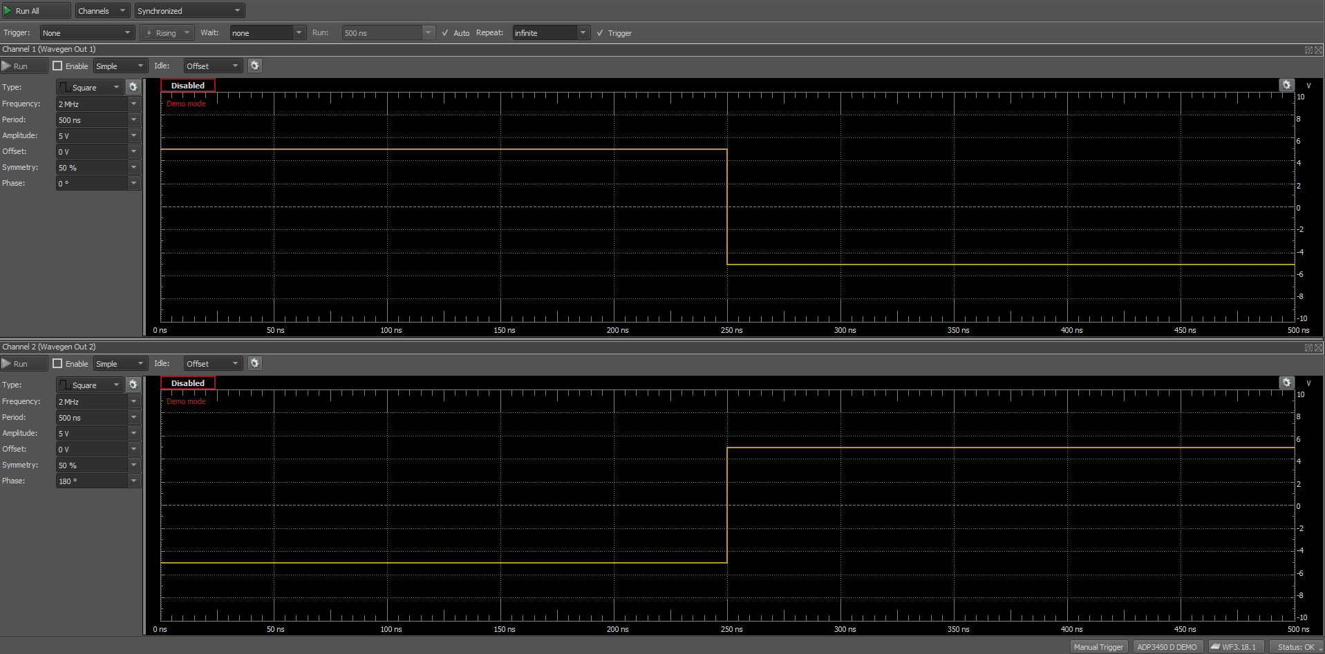
Both channels will use the same settings, a square wave with the following characteristics:
        Frequency: 2 MHz
        Period: 500 ns
        Amplitude: 5 V
        Offset: 0 V
        Symmetry: 50 %
        Phase: 0 º for Channel 1
               180 º for Channel 2
Patterns:
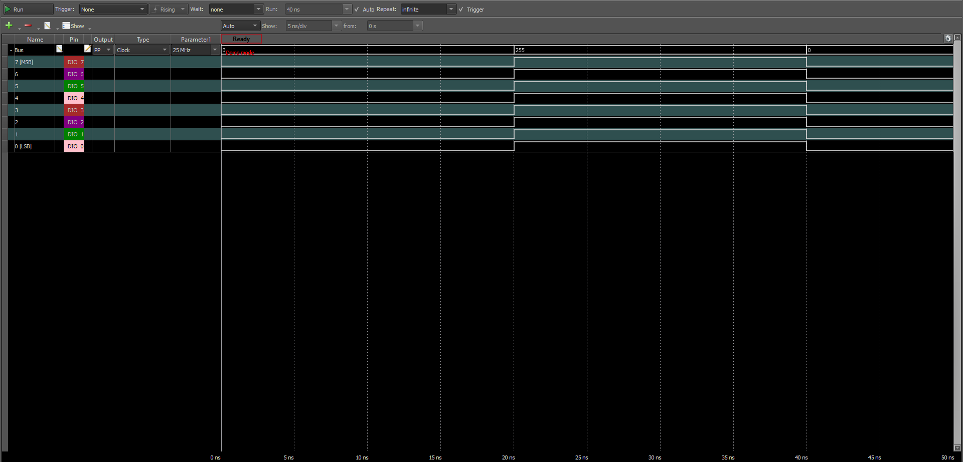
In order to stress the digital part of Analog Discovery 2, we need to add in the Patterns tab a bus that uses the first eight DIO ports. All of the ports are set to output a clock signal at a frequency of 25 MHz.

Logic:
The patterns generated above are read back using the other eight DIO ports.
Supplies:
The power supply outputs will be set to 4 V and -4 V for the positive and negative supplies, respectively.
DAQami
To set the interface and view the data collected by USB-TC, we have two options when opening the DAQami software. After selecting “New Configuration”, a two-button window will appear on the screen, automatic and manual. If the automatic button is selected, DAQami will create a chart with all the ports it detects that are in use. For this project all the charts will be created manually, select and click the “manual” option. The next steps are to add new channels and rename them.
On this screen select the tab “Channels”, from here we can select and rename the used channels and digital ports.
Both the WaveForms and DAQami workspaces are saved and available at the end of the article.
Hardware Setup
Test Circuit
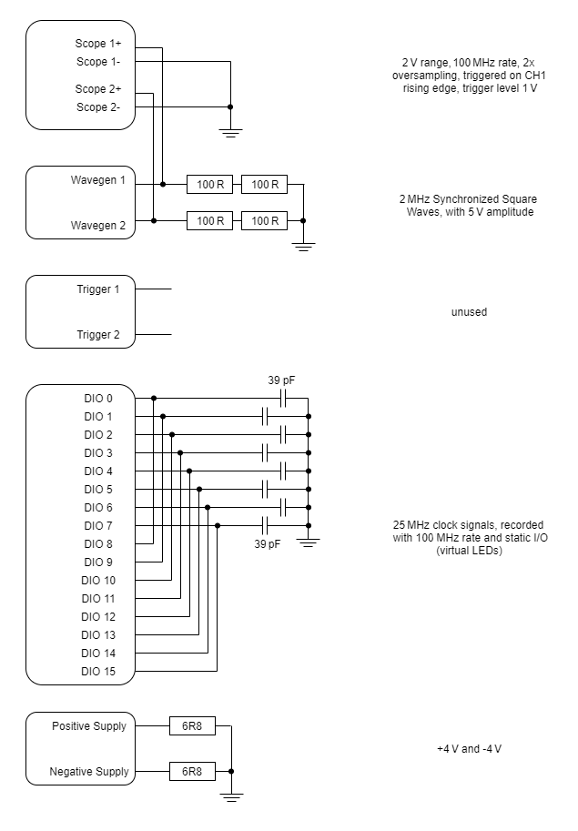
To thermally stress the Analog Discovery 2, the circuit in the next figure will be implemented. The oscilloscope channels will be connected to the signal generators in parallel with a pair of 100 Ω resistors in series on each signal line. Thus there is a resistance of 200 Ω for each channel. Triggers are not used, so they will not connect to anything.
Each power supply, positive and negative, will be connected to a power resistance of 10 W and 6.8 Ω.
The first eight digital input/output ports will be connected to a 39 pF capacitor and the other eight will be connected to read the signal from a capacitor. Each capacitor has the role of simulating the input of digital circuits, the more digital circuits are connected, the higher the capacitance. Thus, the capacitor simulates a non-ideal digital circuit.
Location of thermocouples
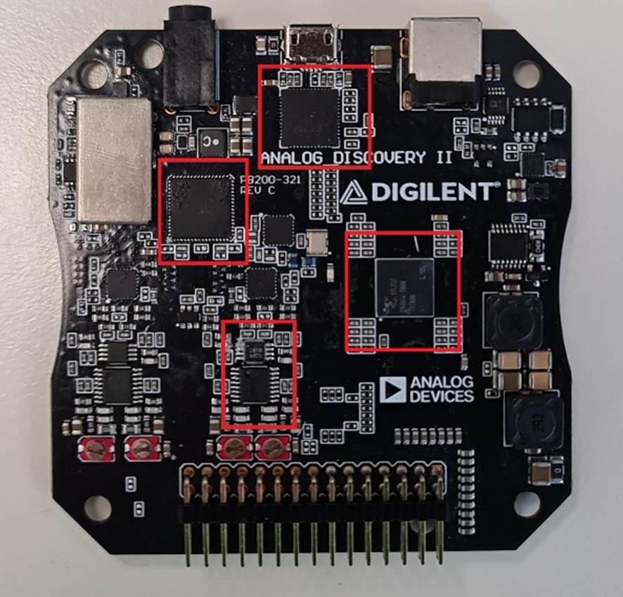
Each thermocouple must be connected to USB-TC as follows: the white wire at CnH and the red wire at CnL, where n represents the port number. For this project, we chose to monitor the following components of the Analog Discovery 2:
- FPGA - Xilinx® Spartan®-6
- Signal Processors Driver - AD9648
- USB Controller – FT232H
- One of the scope channels – AD8066
After connecting all the probes and the test circuit, the setup looks something similar to the one in the picture. An enclosure has been created for this project to keep the thermocouples in place.
Interpreting Captured Data
As mentioned above, due to their location on PCB, they are located on the bottom of the Analog Discovery boards. User sources are measured separately just with a thermal camera. Because of the way the PCB is constructed, the heat emitted by the chips from user sources is felt by the chips measured in this project. These chips can reach a temperature of up to 70 ℃, For this reason, I measured with them turned off and made measurements as they were turned on, this is marked on the graph with the red border. When turned on, all chips have an increase of about 10 ℃. These increases are due to the following aspects: they share the same PCB and copper ground plane which conducts heat
FPGA - Xilinx® Spartan®-6
Depending on the room temperature, the FPGA stays at around 30 ºC. Using all the instruments, apart from user sources, the temperature recorded with the USB-TC is stable at 44 ºC. But if the user sources are also turned on, the measured temperature increases by 10 ºC.
Signal Processors Driver - AD9648
AD9648 is a 10-bit signal processor that includes a complete analog front end with A/D conversion.
From the datasheet provided by the manufacturer, the operating temperature has a range between -20 ºC and +85 ºC. As in the case of FPGA, this chip takes the heat emitted by the user sources circuit. At full load, the surface of the chip is at a temperature of 42 degrees Celsius, after the starting of the user supply, its temperature rises to 45 ºC.
USB Controller – FT232H
The FT232H is a single-channel USB 2.0 Hi-Speed to UART/FIFO IC. In full load, depending on the position of the thermocouple, a maximum temperature of 58 ºC was measured. This is just a hot spot from the chip surface, after applying the thermal pad temperature was between 50-55 ºC. And with user sources off, its temperature was like that of AD9648, more precisely around 42 ºC.
Scope Channels – AD8066
AD8066 are voltage feedback amplifiers that offer ease of use and high performance. They are rated to work between −40 °C to +85 °C. This chip is used to transmit the signal read on the oscilloscope channels to the analog-to-digital converter. It works on full load at a temperature of 38-39 ℃. Even if its position on the PCB is completely opposite to user supplies, the heat emanating from these is still felt, but less compared to the other measured chips. Thus there is an increase of 3-4℃, this is marked on the graph with a red border.
Tips to improve the accuracy
Thermocouples have a very small contact area, often thermocouples used in this demo take over the ambient temperature. For a single use, it is good to use thermal paste instead of a thermal pad. The only problem is that it dries in prolonged contact with air.
This project only demonstrated one scenario of using a USB-TC. In other scenarios using the same thermocouples, their performance will increase, without the need to use reasonable thermal conductive solutions, to surround the contact surface with the heat emitted by the monitored object.
Workspace
Here are the work spaces for the two software used: ad2_termal.rar
Next Steps
For more guides on how to use your Test and Measurement Device, return to the device's Resource Center, linked from the Test and Measurement page of this wiki.
For more information on the Aanalog Discovery 2 visit the Resource Center.
For more information on USB-TC visit the USB-TEMP and TC Series.
For technical support, please visit the Test and Measurement section of the Digilent Forums.


