Getting Started with the Current and Power Adapter
Overview
This guide will get you started with your new Analog Discovery Current and Power Adapter, from getting it out of the box to taking your first measurement.
Inventory
- Your new Analog Discovery Current and Power Adapter
- A computer, with the WaveForms application (version 3.21.3 or later) installed.
- A compatible Digilent Test and Measurement device, typically an Analog Discovery 3
- If you have never used the Analog Discovery 3 before, we highly encourage going through the dedicated Analog Discovery 3 Getting Started Guide
- The Reference WaveForms workspace
- A power source to be analyzing
- This tutorial uses a Discovery USB Programmable Power Supply (DPS3340) as it can provide both static and modulated DC power.
- A load for your power supply
- This tutorial uses a Basys 3
Guide
1. Unboxing
Take out your Analog Discovery Current and Power Adapter out of the packaging it arrived in.
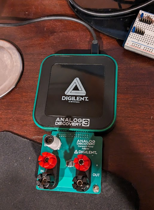
- Take note of the 2×15-pin connector, the pair of red and black banana jacks for input and output power, and grey barrel jack with a green ring for reference ground.
2. Take a Measurement
This section walks through using the Analog Discovery Current and Power Adapter for the first time. The guide presumes that you are already familiar with using the Analog Discovery 3 and the WaveForms software. An Analog Discovery 3 Getting Started Guide is available if you have not used the AD3 or installed the WaveForms software before.
In this demo for the Current and Power Adapter, a Discovery Power Supply (DPS3340) is used as an external power source for a Basys 3 running its out-of-box demo acting as the load. If you do not have these particular items, other applications that are safely set up can also be tested that are within the Specification limits.
If you are not certain about your set up or application, please reach out on the Digilent Forum, https://forum.digilent.com/forum/8-test-and-measurement/, where one of the Digilent engineers, such as the author of this reference page, will be able to help you.
Caution!
Take care to ensure that signals measured fall within specified input ranges and do not exceed the specified overvoltage protection range. Do not use the Current and Power Adapter for measurements within Measurement Categories II, III, or IV. For example, do not use the adapter to perform measurements on circuits directly connected to a standard wall outlet, building installations like circuit breakers, or power lines.
- Take a Measurement - Steps
-
Plug in the Current and Power Adapter
Plug in the Current and Power Adapter to your compatible Test and Measurement device. Connect that device to your host computer via its USB cable.
Set up the Power Source
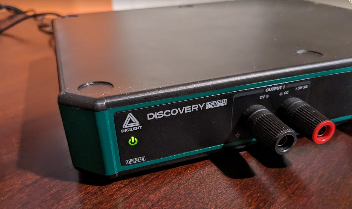
Connect the 19 V external power supply and USB cable to the DPS3340 and switch it on.
Connect the System Grounds
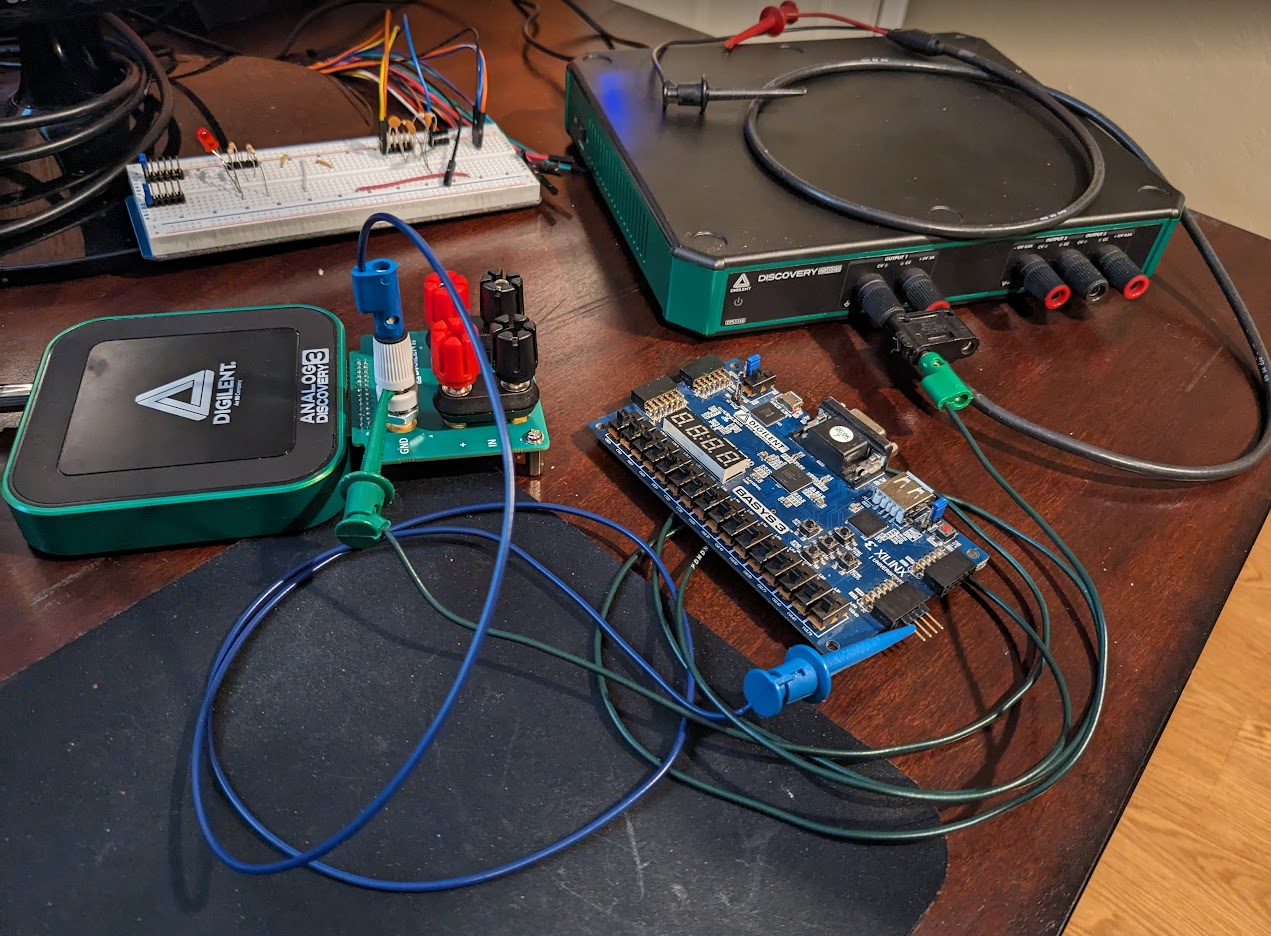
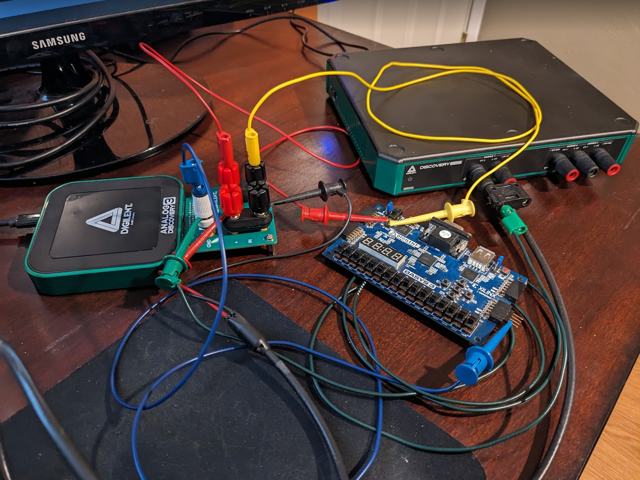
Connect the grounds between the power source, Adapter, and load that is to be driven to establish a common voltage reference between the three systems.
While not strictly necessary for this particular demo setup in this tutorial, switch off the DPS3340 and the Basys 3 before connecting the three grounds together.
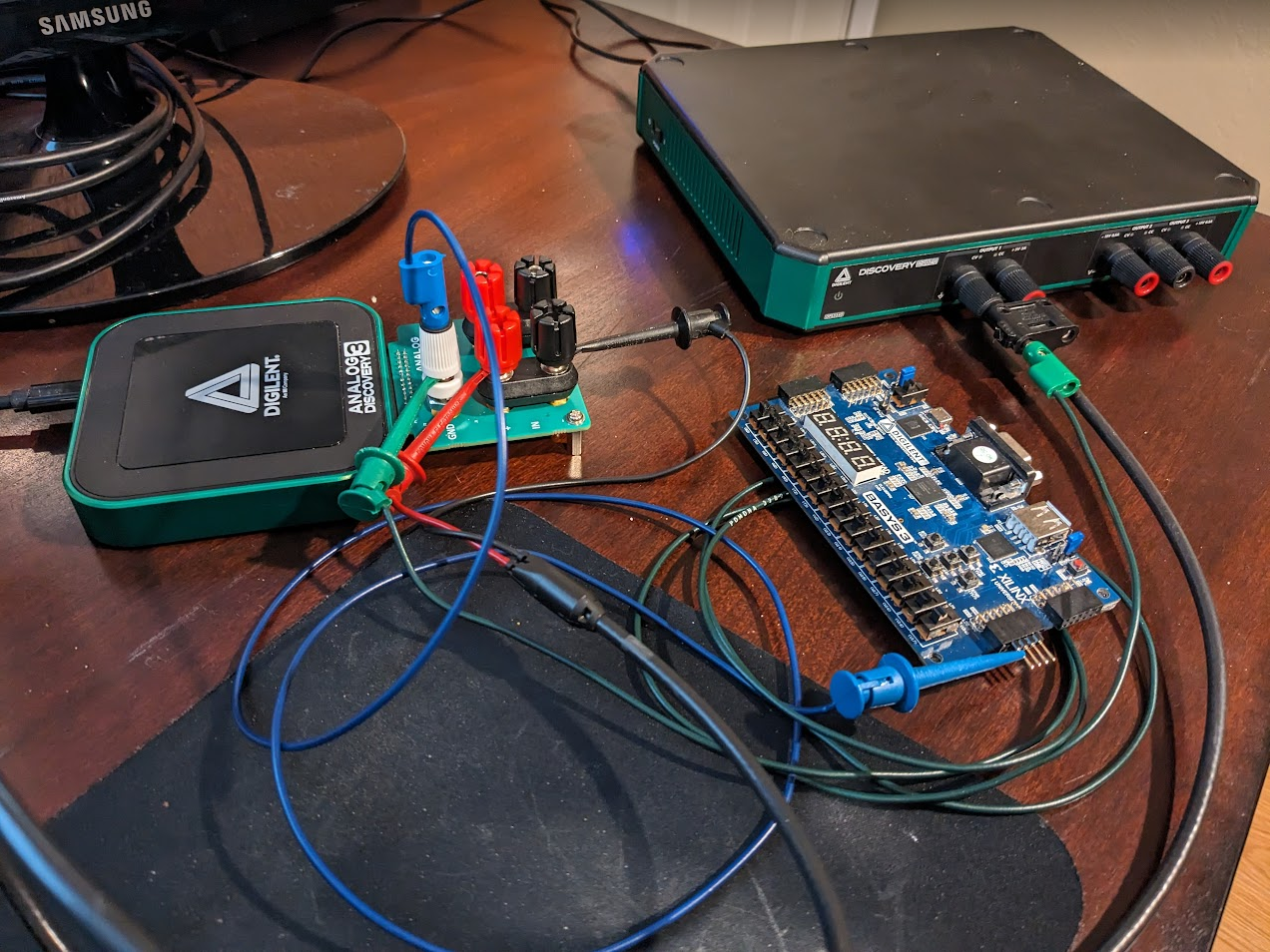
The DPS3340 ground is present on each of the black banana connectors and is shared with its USB connector (it is isolated from the network through the external power supply). Connect the ground from the black connector on Output 1 on the DPS3340 to the dedicated singular system ground (labeled “GND”) on the grey banana connector on the Current and Power Adapter. Similar to the DPS3340, the system ground on the Current and Power Adapter is connected to the Analog Discovery device's ground which is also connected to the USB ground on the host computer.
A connection should also be made from the grey banana connector on the Adapter to a ground point on the Basys 3. I choose a ground pin on one of the Pmod host ports, using a pin header to help ensure that no accidental short occurred with the nearby 3.3 V rail.
Connect the Power Source to the Adapter
Connect the positive lead of the power supply (the red ringed connector on Output 1 of the DPS3340) to the red IN(+) binding post on the Adapter, and the negative/ground lead of the power supply to the black IN(-) binding post on the Adapter. Because the attached Analog Discovery device supports ±25 V with respect to ground on each of its analog input channels (and thus also small AC signals), the leads of the power supply can be reverse with regards to which Input binding post they are attached to, but the reference workspace will then report that it is measuring a negative current and power draw on DC power supplies, which is almost certainly not the result you expect to see.
Connect the Adapter to the Load
It is best practice to ensure that the power supply and the load are both switched off before connecting the Adapter to the Load.
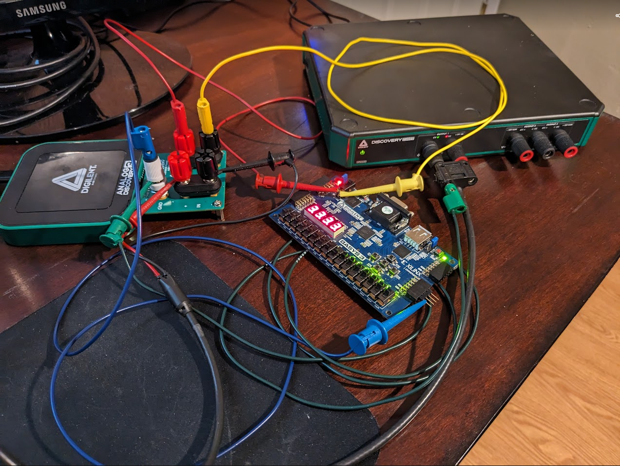
For this particular demo using the Basys 3 as a load, set JP2 (next to the power switch) to the EXT setting and set JP1 (next to the red PROG button) to the QSPI setting. Then connect the black Out(-) binding post to the 'GND' pin on the 1×2 external power supply MTE header just below the power switch (yellow banana to minigrabber cable in the photo). Then connect the red Out(+) binding post to the 'EXT' pin on that same header.
While the silkscreen of the Basys 3 states “5V only!”, this demo takes advantage of the fact that when the USB Host port on the Basys 3 is not being used, the supplied power to the Basys 3 can range between 3.6 V and 5.5 V, making it an ideal candidate to easily observe how different supply voltages affect the required current draw for operation.
Turn on the Power Source and Load
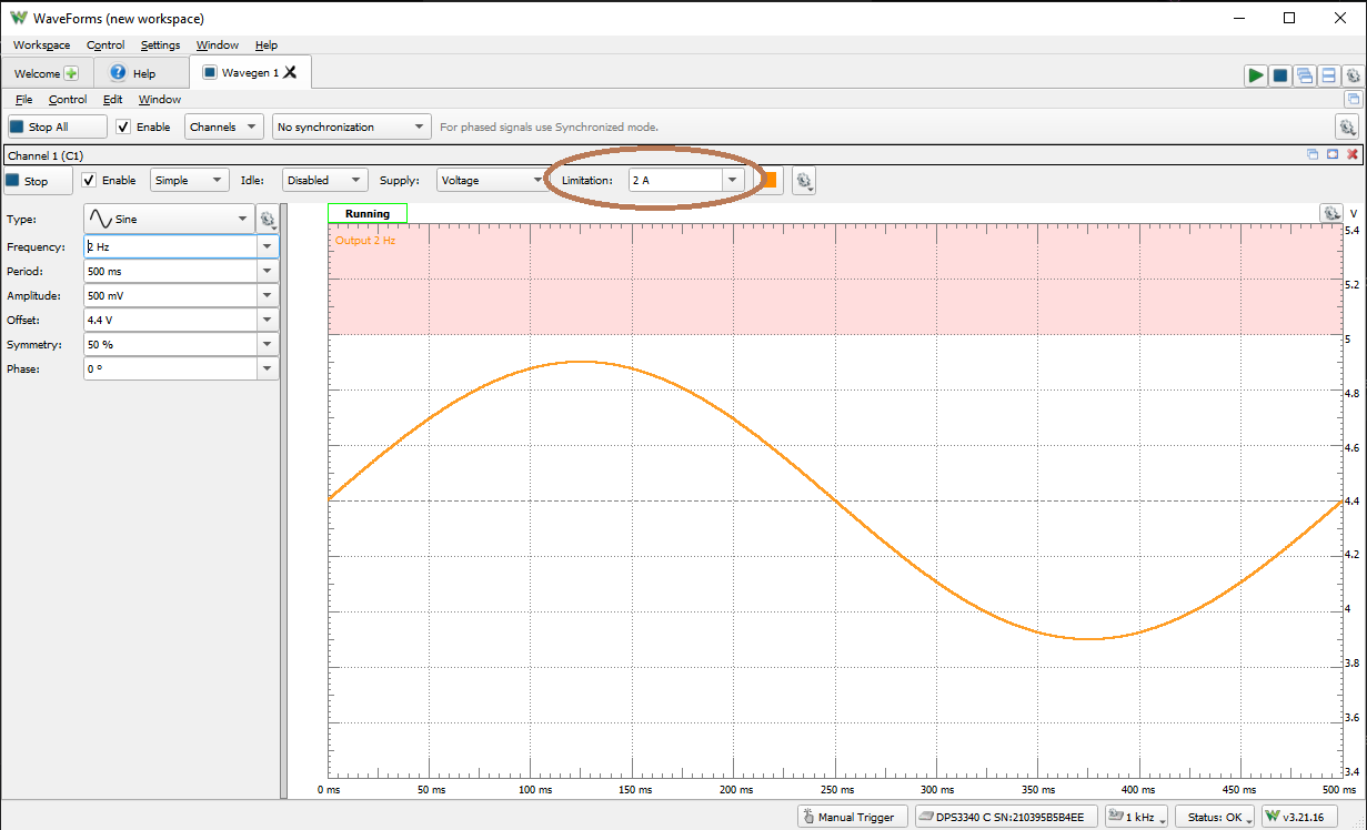
Your steps may vary depending on your chosen power supply and load, but for this demo, open up a new instance of WaveForms and connect to the DPS3340. Select the Wavegen instrument and change the settings on Channel 1 to create a 2 Hz sine wave with an offset of 4.4 V and an amplitude of 500 mV.
Be sure to also change the current output limitation from 100 mA to 2 A, otherwise the Basys 3 will not turn on due to insufficient power.Then, after double checking that the jumpers on the Basys 3 are set to EXT power and QSPI, flip the power switch to the on position. The Basys 3 should now be lit up and running.
Using the Current and Power Adapter Workspace
Now that the hardware setup is finally complete, it's time to use the workspace. Aside from changing some settings to make your viewing experience more convenient for your particular setup, the workspace is largely “plug and play”. Figure 9 shows the recommended things to double check when using the workspace.

Figure 9: Numbered image of what to check in the Reference Workspace. - Open a new instance of WaveForms, connect to the connected Analog Discovery device, and open the reference workspace provided in the Inventory: Workspace/Open/ (upper left corner)
- WaveForms will ask you if you want to open this workspace with your Analog Discovery device as opposed to the particular device on my desk. Choose “Yes” to proceed.
- Make sure the positive Supply voltage is correctly set to 5V and the negative supply disabled. (lower left quadrant)
- Click the green Run All instruments arrow. (upper right corner)
- Select the visualization instrument: Scope vs Spectrum. (left edge)
- Run the selected visualization instrument. The other one will stop automatically. (upper left quadrant)
Additional steps if you are observing an AC signal
- Set the appropriate time base to fit more than a period within the View plot. To see the time base settings, scroll the channel window upwards. (right edge)
- Adjust the vertical scaling of channels v, i, p as convenient to your system. (right side)
- Set the Current range as appropriate: 0 for 25 A, 1 for 12.5 A, 2 for 5 A, 3 for 2.5 A. (bottom middle)
- Verify the Current range setting. (upper right quadrant)
- Set Cursors T1 and T2 to fit an exact integer number of periods, ideally where the voltage crosses the zero value. (middle x2)
- Observe the scope plot and the Measurements values. By default, the light blue trace is the calculated instantaneous current, the yellow trace is the measured voltage, and the red trace is the calculated power.
- Add/modify the displayed Measurements and viewing settings as convenient by right clicking on a line item and choosing Edit.
- Additional information about each of the calculations is provided in the Current and Power Adapter Reference Workspace User Guide.
- Save the modified workspace with altered name (to keep the original unchanged).
Common issues with the workspace and how to resolve them:
- In the Measurements window, the Reactive Power (Q) and Phase shift of Current relative to Voltage (variant Phi) list a “Syntax Error”
- This is likely occurring because you are using shift or scan mode at a low sample rate. The two calculations in question are based the values between the time cursors. Unlike Repeated mode, where the whole buffer of data is collected before being rendered and then calculated upon, Scan and Shift modes fill up their data over time, resulting in a situation where WaveForms is trying to calculate on data that hasn't come in yet. Once the Scope Plot is filled with data, simply right click on the Measurement line item with the Syntax Error, choose Edit, then click okay without changing anything at all to resolve the issue.
- My current and power in the plot seem to be flat instead of fluctuating like I would expect with my variable power input.
- Make sure the positive 5 V supply is enabled.
- I clicked run all but nothing is happening
- Check to see if the Scope instrument started running.
- Confirm that your load is ready to receive power and isn't switched off.
- If you adjusted the timebase to be much wider, change the Scope mode from Repeated to Scan or Shift so that WaveForms isn't collecting all 5 or 10 seconds worth of data before displaying it on the screen.
In the non-numbered image shown in Figure 10, you can see an example of the Reference Workspace analyzing the voltage and current being provided to the Basys 3 from the slowly oscillating supply from the DPS3340, with the offsets and vertical scaling adjusted for viewing convenience.

Figure 10: The Reference Workspace observing the Basys 3 being powered by the DPS3340. The sharp changes in current and power that occur once a second are when the four digits of the 7-segment display change numbers, such as from displaying all 7's (which only uses 3 segments) to all 8's which use all of the segments. You can also see that as the voltage that is being supplied to the Basys 3 increases, the amount of current being drawn decreases as the amount of power being used by the FPGA is not fluctuating with supply voltage.
Next Steps
To find additional reference materials on the Current and Power Adapter, please visit the Current and Power Adapter Resource Center. For reference material and guides on the Analog Discovery 3 and WaveForms, please visit the Analog Discovery 3 Resource Center.
For detailed steps about how to install and use WaveForms on Raspberry Pi, follow this guide: Getting Started with Raspberry Pi and a Test and Measurement Device.
For technical support, please visit the Test and Measurement section of Digilent Forum.


