This is an old revision of the document!
Building a MIDI Controller with Analog Discovery Pro (ADP3450/3250)

This page is under construction.
A Musical Instrument Digital Interface (MIDI) controller is a key element in electronic music production. Such devices, both hardware and software, can be quite expensive, but with a bit of work, the Analog Discovery Pro can be set up as a highly customizable MIDI controller, with wireless connection capability. This guide presents, how to configure your Test & Measurement device and your computer to be able to send and receive MIDI commands over Ethernet or Wi-Fi.
Prerequisites
Hardware
- Arty S7, or other FPGA development board
- hardware user interface elements (buttons, switches, sliders, etc.)
- passive electronic components
Software
- On PC:
- BandLab, Serato Studio, or any other DAW of your choice
- Tera Term, or any other terminal emulator of your choice
- Visual Studio Code, or any other editor of your choice
- Multisim Desktop Education version 14.2, or higher
- Vivado version 2021.1, or above
- Adept - optional
- WinSCP - optional
- On Analog Discovery Pro:
- RaveloxMIDI - installation instructions can be found below
- Python 3 - preinstalled
- WaveForms SDK - preinstalled
What is MIDI? What is RTP-MIDI? What is a DAW?
Musical Instrument Digital Interface (MIDI) is a technical standard which is used in electronic music production. MIDI controllers are not instruments, they do not produce sounds, but a send a specific set of commands to other devices, or software, like a Digital Audio Workstation (DAW). These commands contain all the information necessary to produce the desired sound, or to apply the desired effect. The most important advantage of a MIDI controller is, that with the same commands, the user can control any instrument of their choice (for example you can “play” a clarinet or a guitar with keypresses).
Connecting a MIDI controller to a DAW usually requires specific connectors. Most laptops do not have such a MIDI connector, nor has the Analog Discovery Pro. While building such connectors is possible, it is simpler to send the MIDI commands over Ethernet or Wi-Fi, using a protocol called Real-time Transfer Protocol - MIDI (RTP-MIDI). RTP-MIDI uses the RTP network protocol to send the commands in real-time to a receiver.
After the MIDI commands are received, they should be “converted” into sound. This conversion is usually done with a Digital Audio Workstation (DAW). A DAW is a hardware or software device which is controlled by MIDI commands and produces audio. In this project the BandLab online DAW will be used, as it is free, and doesn't have to be downloaded.
Signal Transmission and Reception
Setting Up the DAW
To connect to your DAW without a physical MIDI connector, you will need a network MIDI driver. Such a driver is included in the rtpMIDI by Tobias Erichsen. Download, install, and start the program, then rename and enable your first session.

Let the rtpMIDI run in the background and open the DAW. Open the DAW's settings, then find the MIDI settings, or MIDI devices and select the previously created rtpMIDI session as an input device.
Add a new track (or more) to your project and select the desired instrument or effect to control.
Before playing the selected instrument, you must set up your MIDI controller.

Setting Up the Analog Discovery Pro as a MIDI Controller
To successfully run this example, you will need the latest Linux version for your device. To update the ADP3450/ADP3250 Linux image, follow this guide: How to Update or Recover Linux Mode on the Analog Discovery Pro (ADP3450/ADP3250).
Now connect your device the internet. If you already have internet enabled for Linux mode, just connect the Ethernet cable and skip this step. Else, follow this guide: Connecting the Analog Discovery Pro (ADP3450/ADP3250) to the Internet.
To command the ADP3450/ADP3250, you will have to connect to it through a terminal. To do so, you will need a terminal emulator program, like Tera Term, PuTTY for Windows, or Serial WiFi Terminal for Android (the Analog Discovery Pro can now be controlled from any device connected to the internet).
Tera Term will be used in this guide, but the steps are similar for each of the mentioned program.
Open the terminal emulator and establish a new Secure Shell (SSH) connection to the Analog Discovery Pro's address: digilent@ADPro. You can leave every other setting as default. When required, enter the user name and the password:
| user name: | digilent |
|---|---|
| password: | digilent |
You should have now a connected terminal.

Install the necessary packages by entering the following command into the terminal:
sudo apt-get install autoconf build-essential libavahi-client-dev libavahi-core-dev libasound2-dev git avahi-daemon -y
When required, enter the sudo password:
| sudo password: | digilent |
|---|
Select the location where you want to work with the “cd” command, then clone the RaveloxMIDI GitHub repository:
git clone https://github.com/ravelox/pimidi.git
Open the cloned directory:
cd pimidi
cd raveloxmidi
Install RaveloxMIDI with:
sh ./autogen.sh
./configure
make
sudo make install

Designing and Building the User Interface
Control Signals
The hardware user interface of the MIDI controller consists of several control elements, like buttons, switches, sliders, drum pads, etc. As these elements need certain conditioning circuits and because the ADP3450 has only 16 digital IO pins, 4 analog input and 2 analog output channels, so the large number of control signals must be multiplexed to the reduced number of inputs, an efficient “driver” must be designed.
The control signals can be divided in three main categories: digital signals (coming from buttons, switches and rotary encoders), slowly changing analog signals (coming from potentiometers/sliders) and fast changing analog signals (coming from pressure sensitive pads). These three categories will be discussed separately, as the methods used to register them differ.
Digital signals can be directly connected in the driver circuit. They must be debounced (the mechanical noise created by the “bouncing” of the pressed pushbuttons must be filtered out) and might be latched (momentary buttons acting like switches). If some signals have to increment/decrement certain counters, these counters can also be implemented in the driver circuit. When the input signals are conditioned, they can be multiplexed to the digital inputs of the ADP.
Slowly changing analog signals can't be directly measured by the digital inputs of the ADP. While the analog inputs (oscilloscope channels) can measure them directly, they should be used to record fast changing analog signals, so another solution should be found. One method to transform the analog signals to digital ones is by using comparators: the comparators can compare the provided voltage level to a fast changing sawtooth signal, and output a PWM signal for which the duty cycle is proportional with the voltage level of the original signal. This duty cycle can be measured on a single digital pin, using the logic analyzer. The generated PWM signal comes connected to the driver circuit to be multiplexed to the digital inputs of the ADP.
- Click for Model and Simulation
-
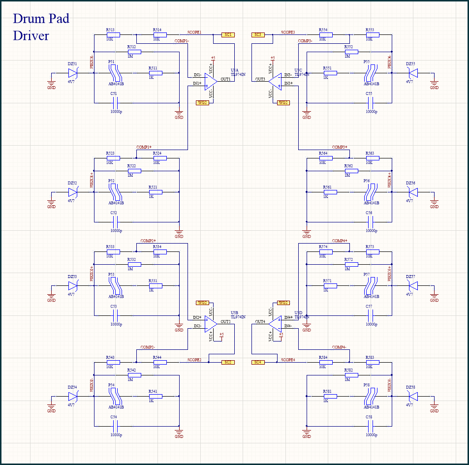
Fast changing analog signals can be measured by the oscilloscope channels. As there will be more signal sources, then channels, these signals have to be multiplexed as well. In the case of the drum pads, the generated pulses are all positive, so the easiest way of multiplexing them is for every channel to add the output of a drum pad to the inverted output of another drum pad. This way the number of input signals will be double the number of input channels and no digital signals are required to control the “multiplexer”. The negative (inverted pulses) can be easily separated from the positive pulses via software. The only downside of this method is, that two simultaneous pulses with equal amplitude can cancel each other, but the probability of this is negligible (humans can't strike two drum pads in the exact same moment).
- Click for Model and Simulation
-
User Interface Design
Design the user interface circuit to contain the control and indicator elements you want. Keep in mind the offered possibilities and limitations of the ADP3450, and the signal conditioning methods discussed above.

For a detailed presentation of the user interface circuitry, you can check the drop-down below, or you can design your own custom user interface.
- The User Interface Circuit
-
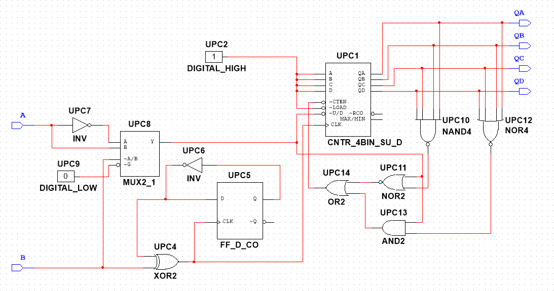
Main Sound Control
The most important control elements are the play/pause button, the record button, the volume slider and the channel selector button. To display the selected channel, this circuit part also contains a double seven segment display.
Four RGB LEDs are also added to lit up this part of the circuit.
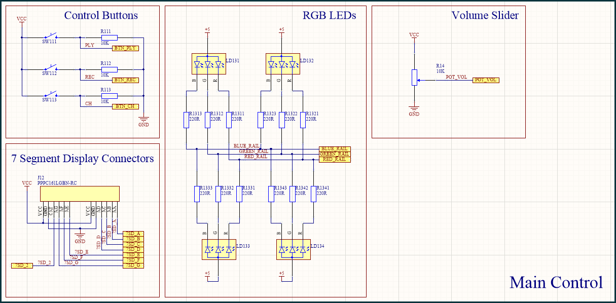
Additional Sound Control
To further shave the sound of the controller, three filters (low, middle and high) are added. The analog-to-PWM converter for the volume slider is present in this block. Incremental rotary encoders are used to set the modulation, the attack, or the release time of the sounds.
The RGB LEDs are also present here, to provide the desired visual effects.

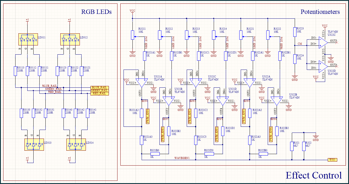
Effect Control
Six potentiometers (with analog-to-PWM converters) are used to control the effects set in the DAW.
Keypad
While traditional keypads have more buttons, this controller only has 12: for the notes C, C#, D, D#, E, F, F#, G, G#, A, A# and B. Two additional buttons can increment and decrement the octave. The index of the chosen octave is displayed on a seven segment display.
The RGB LEDs are connected to a connector for an open-drain MOSFET driver module.

Drum Pad (Driver)
The actual drum pads are mechanical parts, each one a disk containing a piezo, but the driver is implemented on the PCB. The outputs of the piezos are clamped and “multiplexed” with the method presented above.


Connecting the User Interface
Connect the output signals of the user interface to the FPGA board, but keep track of the connections, as they will have to be defined in the PLD design later, in Multisim (see below).
The BNC oscilloscope connectors are connected directly to the drum pad outputs (multiplexed) and the waveform generator channels are used to generate the reference signal for the PWM generator and the -5V DC voltage reference. The USB ports on the ADP are used to power and program the FPGA, connect the Wi-Fi dongle and supply power to the displays and LEDs through a USB connector.

The Pmod connectors are used on the Arty-S7 to connect the user interface control elements, while the Chipkit analog headers are used to connect the displays and the LEDs. The ADP3450 digital pins are connected to the outer digital Chipkit header.

Driver Design
As most of the control signals are digital (including the converted “slow” analog signals), the conditioning circuits for them will be also digital. To prototype a complex digital circuit, the easiest way is to use an FPGA development board. In this project the Arty-S7 FPGA board will be used, for which the design will be created in Multisim, to avoid using VHDL, or Verilog (which can be challenging, especially for new users) and to make the final circuit easier to understand by drawing a schematic of it.
If your chosen FPGA board isn't available in Multisim PLD design, follow the instructions in the Adding Digilent FPGA Boards to Multisim guide to create the configuration files for it.
Start a new PLD design in Multisim, select your board and create the conditioning circuits for your signals. You should use some digital I/O pins of the ADP3450 as outputs to control the multiplexers connected to the input pins, this way you can connect much more signals to the input, then the number of input pins.
When ready, click Transfer → Export to PLD… → Generate and save programming file to use Vivado and compile the bit file from the design.

For a detailed presentation of the driver circuitry, you can check the drop-down below, or you can design your own driver on an FPGA board.
- The Driver Circuit
-
Hierarchical Blocks
Before creating the driver, design and test certain circuits which will be used multiple times in the driver, to make your final design easier to create and to understand.
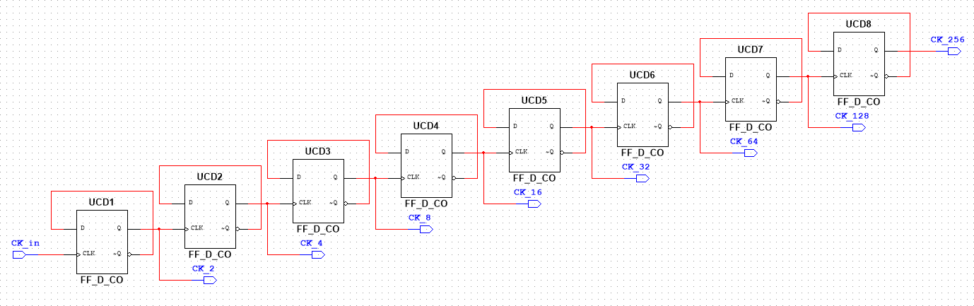
The first hierarchical block created is the clock divider. Several D flip-flops are used to reduce the clock frequency to the desired value. If the clock rate must be further reduced, multiple clock divider blocks can be cascaded.
One of the most important building blocks is the debouncer. When a button is pressed, some mechanical noise appears in the signal (the bouncing of the two metal plates on each other), so if the action is taken on the edge of the signal, the circuit will be triggered multiple times. A debouncer “validates” the output signal only after a certain time, so the bouncing can come to an end before.
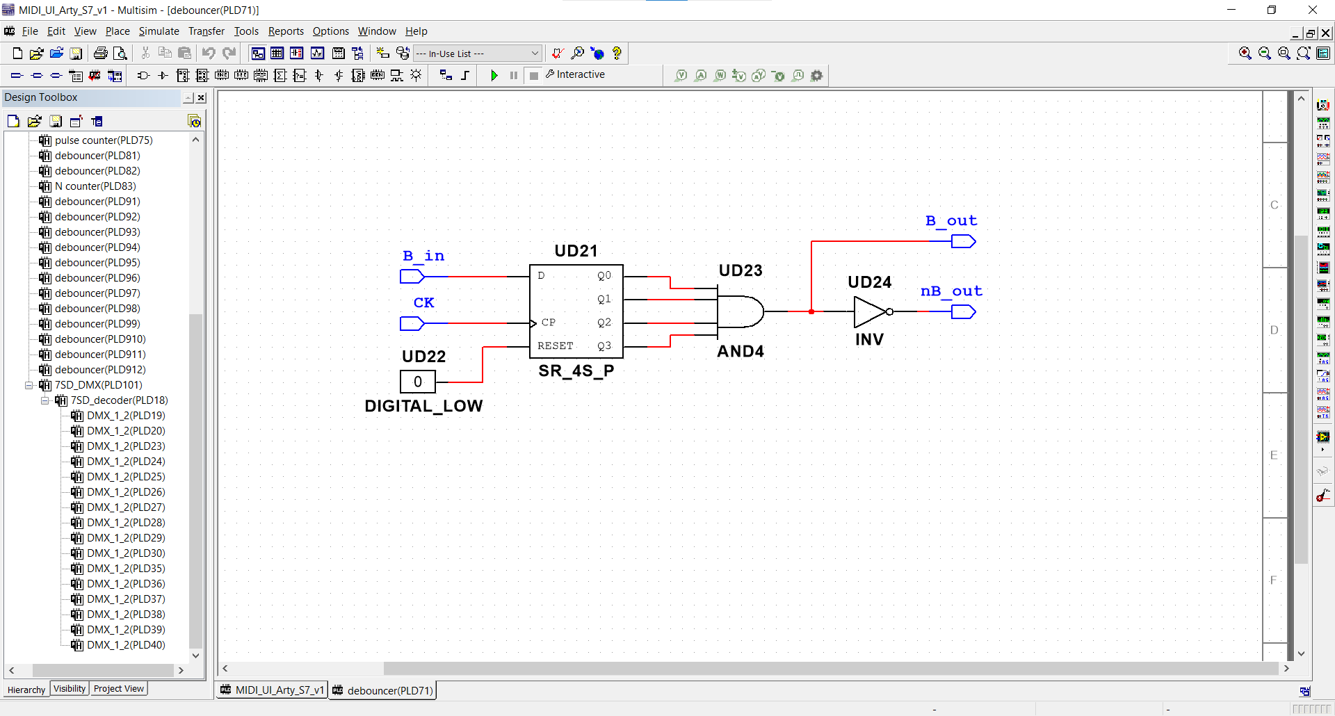
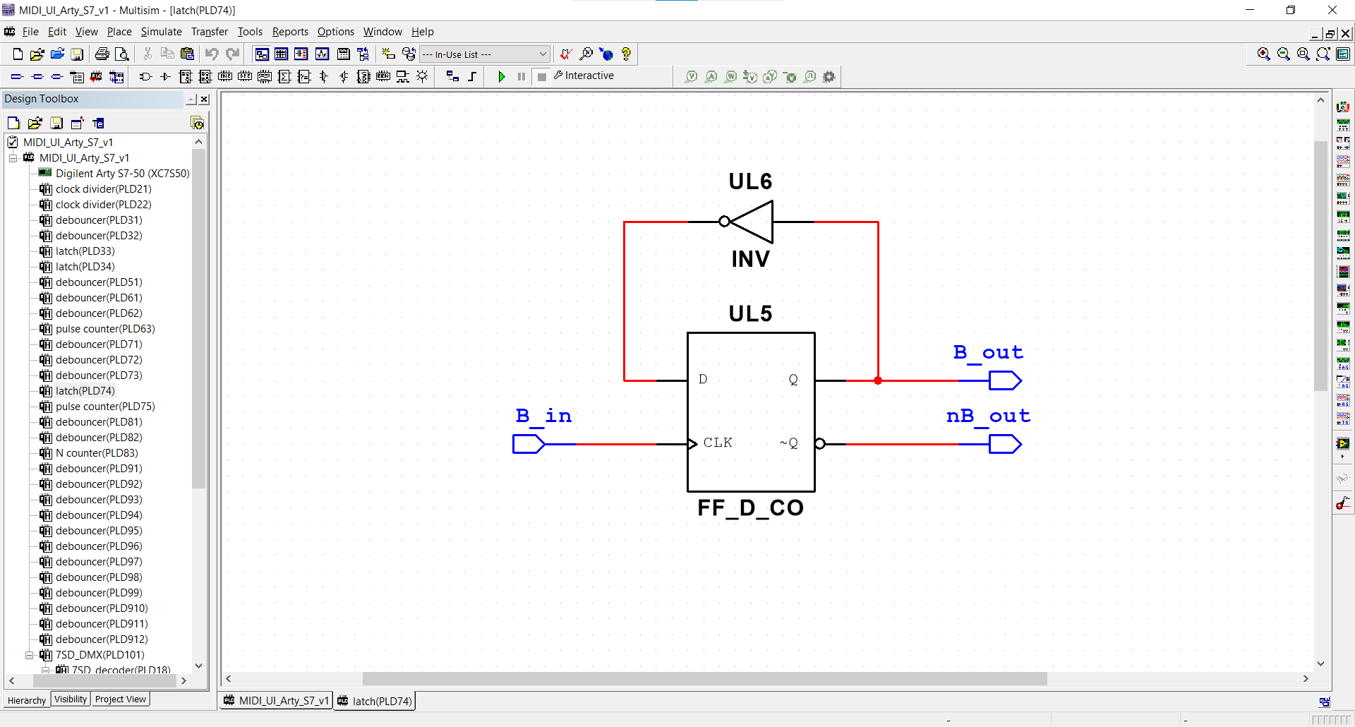
A simple latch should also be implemented, so buttons can be used as switches (on press turns the signal high, the next one turns it low).
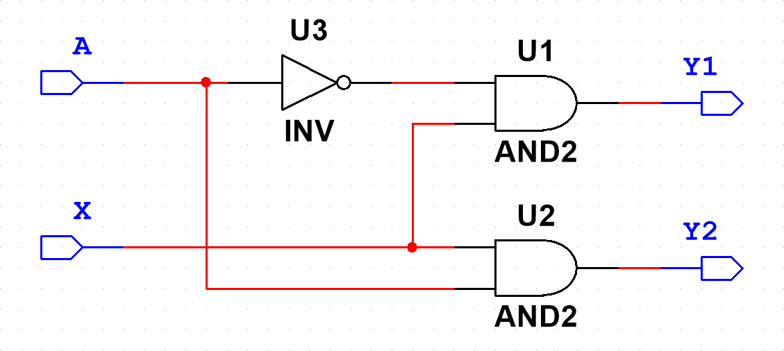
A 1:2 demultiplexer is also implemented as Multisim contains only larger circuits (1:8).
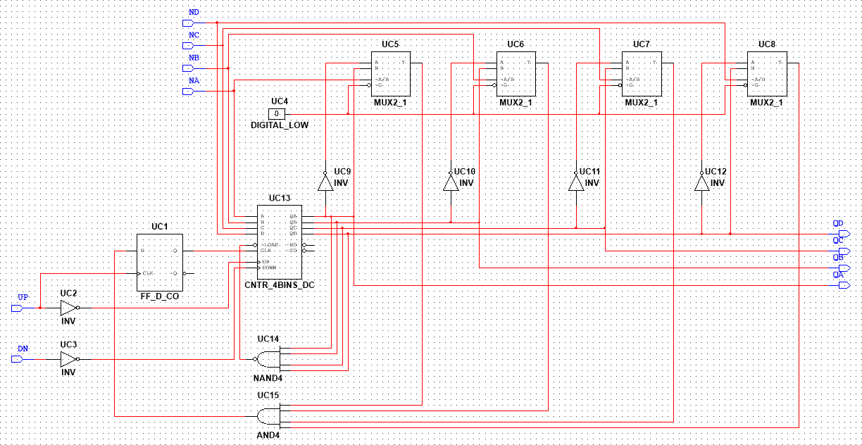
The next block to be prepared is an up-down counter to N (0<N<15). This circuit will be used to change the octaves (there are only 11 valid octaves, so counting to 15 is unnecessary).
As the Python script will use polling to measure every signal, it might miss certain events of the rotary encoders, so they should be re-encoded as numbers. This is why a pulse counter is designed, which is an up-down counter clocked by the two waves of the rotary encoder in quadrature. The block turns the incremental rotary encoders into 4-bit absolute encoders.
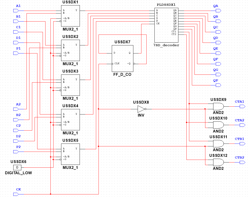
While 4-bit binary numbers might be easy to understand for machines, on a user interface (created for humans) numbers should appear in decimal representation. This is why a decoder must be used for the dual 7 segment displays, which displays a number between 1 and 16 (received in binary) in decimal representation.
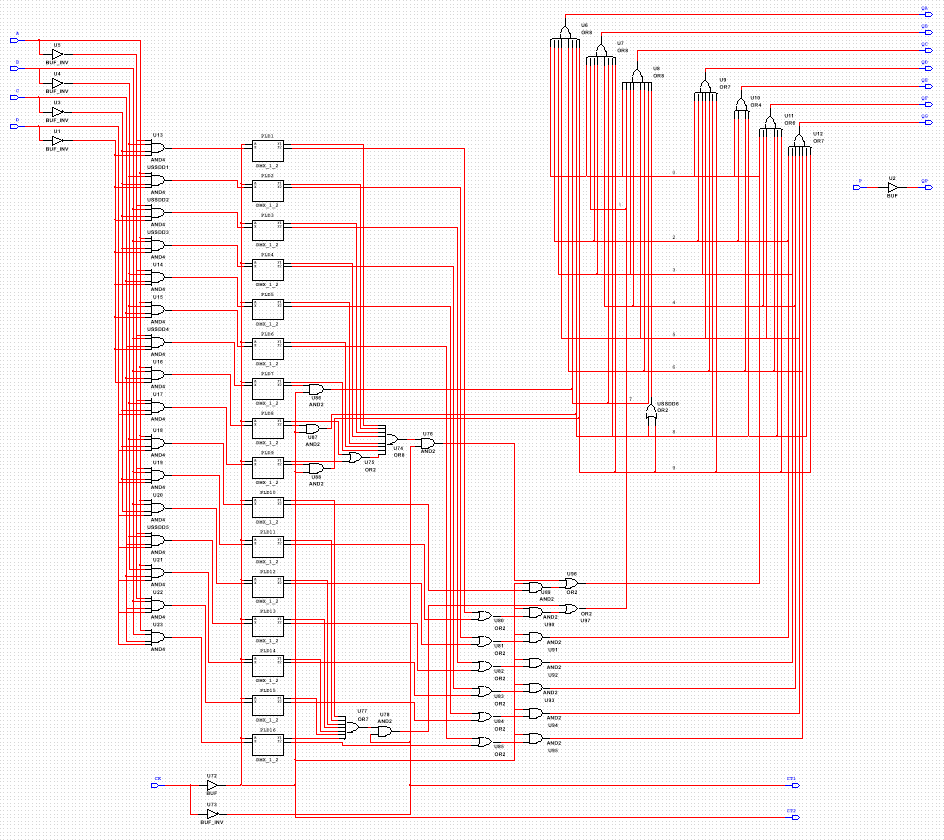
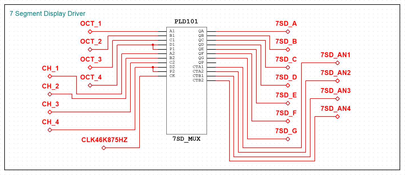
While most FPGA boards have many pins, there are some cases, when “many” is still not enough. This is why the cathodes of the two dual displays should be multiplexed (the same cathodes are used in different times). This block takes two binary numbers (and one clock) as inputs and displays the first number on the first display (decoded) and the second number on the second display.
Driver
After all the blocks were designed and tested, the actual driver can be built.
As almost all conditioning circuits need clock signals, the derived clocks (with the desired frequency) must be obtained from the FPGA clock. Use clock dividers to reduce the frequency.

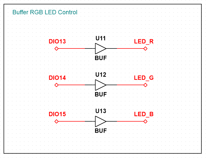
The RGB LED control signals are just passed through the FPGA, they are entirely generated by the ADP.
The play/pause and record buttons are debounced and latched to act like switches.

The PWM signals coming from the potentiometer conditioning circuits are again buffered, then sent to the multiplexers.

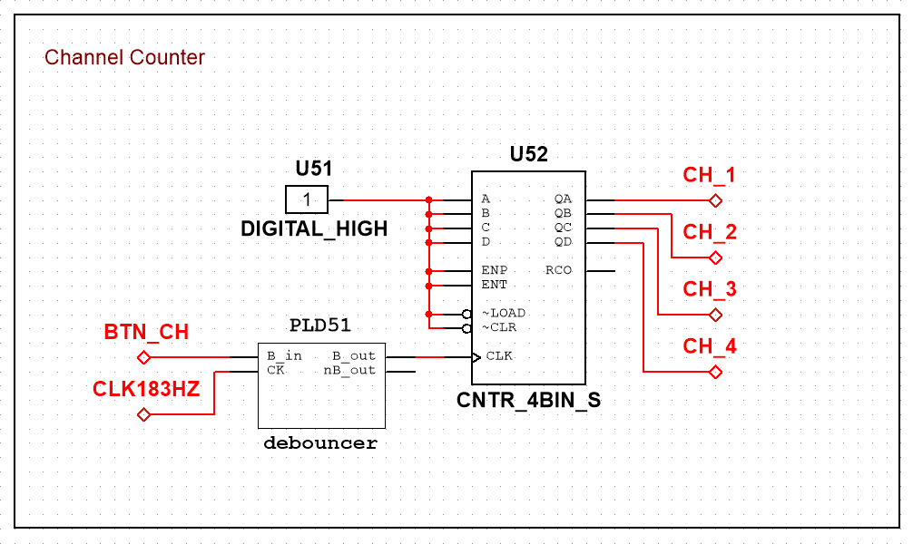
The button selecting the MIDI channel is debounced, then connected to an up counter. The output of the counter is connected to the multiplexers.
The pulse counter block is used to turn the incremental encoder used as modulation wheel into an absolute encoder.

The same is done for the timing wheel, but the latched timing button decides, if the output is used for the attack time, or for the release time (the distinction is made from software).

Octaves are set by two buttons: one buttons shifts the octave up, the other one down. The N counter block is used to set the upper limit of counting to 10 (the block will count from 0 to 10 - 11 positions).

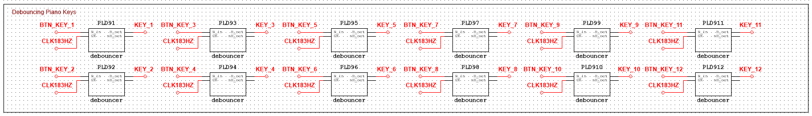
The piano keys are debounced and sent to the multiplexers.
The previously created hierarchical blocks are used to display the channel number and the octave index on the 7 segment displays.
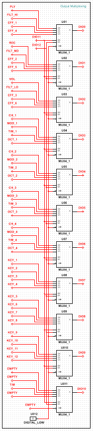
Finally, the conditioned output signals are multiplexed (4:1) to the digital I/O pins of the ADP. To generate the multiplexer addresses, two digital pins of the ADP are used, the address being generated from software.


Connecting the Driver
In Multisim, define the connections between the FPGA board and the ADP.

Designing the Software
Hardware Abstraction Layer
To make the program simpler and easier to understand, a sort of Hardware Abstraction Layer (HAL) is needed: a set of functions, which communicate with the hardware, and make the usage of the hardware easier. In this case the WaveForms SDK is used to control the ADP3450, but to further simplify the final script, the module created in the Getting Started with WaveForms SDK guide will be used.
Configuring the FPGA
To configure the FPGA board connected to the ADP3450, with the bit file created with Multisim, the Adept Utilities must be installed on your device. To install the software, follow the Programming an FPGA Board with the Analog Discovery Pro (ADP3450/ADP3250) guide.
Create a module in which you use in a subprocess the commands
djtgcfg init -d ArtyS7
and
djtgcfg prog -d ArtyS7 -i 0 -f ./FPGA/midi_driver_ArtyS7.bit
Note: Don't forget to change the device name and the name of the bit file to match to your preferences.
""" This module realizes communication with the FPGA board """

from subprocess import Popen, PIPE

"""-------------------------------------------------------------------"""
""" UPLOADING THE BIT FILE """
"""-------------------------------------------------------------------"""


def configure(description_file="./FPGA/MIDI_UI_Arty_S7.bit", device_name="ArtyS7", chip_index="0"):
    """
        configures the connected FPGA board

        parameters: - bit file
                    - device name
                    - chip index

        returns:    - True on success, False on error
    """
    # initialize the FPGA board
    process = Popen(["djtgcfg", "init", "-d", device_name],
                     stdout=PIPE, stderr=PIPE)
    stdout, stderr = process.communicate()
    stdout = stdout.decode("UTF-8")
    stderr = stderr.decode("UTF-8")

    # check response
    if stderr != "" or not ("Found Device ID" in stdout):
        return False

    # upload the bit file
    process = Popen(["djtgcfg", "prog", "-d", device_name,
                     "-i", chip_index, "-f", description_file],
                     stdout=PIPE, stderr=PIPE)
    stdout, stderr = process.communicate()
    stdout = stdout.decode("UTF-8")
    stderr = stderr.decode("UTF-8")

    # check response
    if stderr != "" or not ("Programming succeeded" in stdout):
        return False

    return True


"""-------------------------------------------------------------------"""
MIDI
Start raveloxmidi in the background as a subprocess, to be able to communicate using RTPMIDI. Use the following command:
sudo raveloxmidi -c ./MIDI/address.conf
Don't forget to change the path of the configuration file, to a file, which contains the bind address: “0.0.0.0”.
network.bind_address = 0.0.0.0
""" This module contains the functions needed to send MIDI messages """
""" More information:
            https://github.com/ravelox/pimidi/tree/master/python """

"""-------------------------------------------------------------------"""
""" GLOBAL """
"""-------------------------------------------------------------------"""


import sys  # interactions with the interpreter
import socket   # socket operations
import struct   # conversion between Python values and C type data
from subprocess import Popen, PIPE # system calls
from MIDI.message import *   # import all MIDI messages

sock = None

"""-------------------------------------------------------------------"""
""" INITIALIZATION """
"""-------------------------------------------------------------------"""


def open(configuration_file="./MIDI/address.conf", localport=5006):
    """
        start ravelomidi

        parameters: - configuration file path
                    - local port
    """
    # start raveloxmidi in the background
    Popen(["sudo", "raveloxmidi", "-c", configuration_file])

    global sock # load variable

    # local variables
    family = None
    connect_tuple = None

    # defining connection parameters
    # code snippet from the RaveloxMIDI examples
    if len(sys.argv) == 1:
        family = socket.AF_INET
        connect_tuple = ("localhost", localport)
    else:
        details = socket.getaddrinfo(
            sys.argv[1], localport, socket.AF_UNSPEC, socket.SOCK_DGRAM)
        family = details[0][0]
        if family == socket.AF_INET6:
            connect_tuple = (sys.argv[1], localport, 0, 0)
        else:
            connect_tuple = (sys.argv[1], localport)

    # connect socket
    sock = socket.socket(family, socket.SOCK_DGRAM)
    sock.setsockopt(socket.SOL_SOCKET, socket.SO_REUSEADDR, 1)
    sock.connect(connect_tuple)
    return
While the background process is running, you can send data sockets containing MIDI data. An extensive list of possible MIDI messages is available on the page MIDI Specification and MIDI CC List for Continuous Controllers.
Open the drop-downs below for the most important MIDI messages.
- MIDI Message Types
-
Message Type Code Meaning Data Byte 1 Data Byte 2 NOTE_OFF 0x80 This message is sent when a note is stopped. Note number Velocity NOTE_ON 0x90 This message is sent when a note is started. Note number Velocity POLY_KEY_PRES 0xA0 Polyphonic Key Pressure (Aftertouch) Note number Pressure CTRL_CHG 0xB0 Sent when a controller value changes. Controller number … PRG_CHG 0xC0 Sent when a patch number changes. Program number - CH_PRS_AFTT 0xD0 Channel Aftertouch Pressure - PITCH_BND 0xE0 This message is sent to indicate a change in the pitch wheel. LSB MSB SYS_EX_START 0xF0 This message makes up for all that MIDI doesn't support. … …
- MIDI Notes
-
Note Value C 0 C# 1 D 2 D# 3 E 4 F 5 F# 6 G 7 G# 8 A 9 A# 10 B 11
- MIDI Octaves
-
Notation Value Meaning DBL_CONTRA_O 0 Starts with $C_{-1}$. SUB_CONTRA_O 12 Starts with $C_{0}$. CONTRA_O 24 Starts with $C_{1}$. GREAT_O 36 Starts with $C_{2}$. SMALL_O 48 Starts with $C_{3}$. LINE1_O 60 Starts with $C_{4}$. LINE2_O 72 Starts with $C_{5}$. LINE3_O 84 Starts with $C_{6}$. LINE4_O 96 Starts with $C_{7}$. LINE5_O 108 Starts with $C_{8}$. LINE6_O 120 Starts with $C_{9}$.
"""-------------------------------------------------------------------"""
""" SENDING """
"""-------------------------------------------------------------------"""


def send(msg_type, channel, data):
    """
        send a message

        parameters: - message type: from MIDI.message
                    - midi channel: 0-15
                    - data: from MIDI.message
    """
    # get data length
    length = len(data)

    # get message length
    byte_count = "B"
    for _ in range(length):
        byte_count = byte_count + "B"

    # construct the message
    # pack a binary structure with all the data words
    message = None
    if length == 1:
        message = struct.pack(byte_count, msg_type + channel, data[0])
    elif length == 2:
        message = struct.pack(byte_count, msg_type + channel, data[0], data[1])
    elif length == 3:
        message = struct.pack(byte_count, msg_type +
                              channel, data[0], data[1], data[2])
    elif length == 4:
        message = struct.pack(byte_count, msg_type + channel,
                              data[0], data[1], data[2], data[3])
    elif length == 5:
        message = struct.pack(byte_count, msg_type + channel,
                              data[0], data[1], data[2], data[3], data[4])
    elif length == 6:
        message = struct.pack(byte_count, msg_type + channel,
                              data[0], data[1], data[2], data[3], data[4], data[5])
    else:
        message = struct.pack(byte_count, msg_type + channel,
                              data[0], data[1], data[2], data[3], data[4], data[5], data[6])

    # send message
    sock.send(message)
    return
When you are finished, kill every process with the name “raveloxmidi” to terminate the connection.
"""-------------------------------------------------------------------"""
""" CLEANUP """
"""-------------------------------------------------------------------"""


def close():
    """
        stop ravelomidi
    """
    # close socket
    sock.close()

    # find remaining processes
    process = Popen(["sudo", "ps", "u"], stdout=PIPE, stderr=PIPE)
    stdout, _ = process.communicate()
    stdout = stdout.decode("UTF-8")
    processes = stdout.split("root")
    processes.pop(0)
    proc_id = []
    for index in range(len(processes)):
        processes[index] = processes[index].split()
        for property in processes[index]:
            if property == "raveloxmidi":
                proc_id.append(processes[index][0])
                continue

    # kill the processes
    success_flag = True
    for pid in proc_id:
        try:
            Popen(["sudo", "kill", "-SIGKILL", pid])
        except:
            success_flag = False
    return success_flag


"""-------------------------------------------------------------------"""
Program Body
Testing
Copy the project containing the Python scripts on the Analog Discovery Pro 3450, with the help of a FAT32 formatted USB flash drive, or using WinSCP.
Navigate into the project directory, then run the script by typing
sudo python3 midi_controller.py
On your PC open the rtpMIDI program, then connect to the directory called “raveloxmidi”. The connection should appear in the participants tab.

Now you can use your wireless MIDI controller, to play any instrument you like - the limit is your imagination. You can expand the capabilities of your controller by adding extra digital and analog control elements, like sliders, more buttons, switches, etc.
Next Steps
The script, the PLD design and the circuit can be modified as needed for your project.
For more information on WaveForms SDK, see its Resource Center.
For technical support, please visit the Test and Measurement section of the Digilent Forums.