Getting Started with Zynq Servers

Overview
This guide will demonstrate creating an Ethernet server application that runs on a Zynq 7000-based FPGA board, such as the Zybo Z7 or Arty Z7. Vivado/Vitis 2023.1 creates the Zynq processor and the server application. The application is called an echo server, and as the name implies, any character sent to it through an Ethernet connection is repeated back to the host.
Prerequisites
Hardware
- Zybo Z7, Arty Z7, Cora Z7 or Eclypse Z7 Development Board
- Ethernet Cat 5 cable
- Micro USB cable for UART communication and JTAG programming
Software
- Xilinx Vivado 2023.1 software suite
- If the Vivado Suite has not been installed, please review the following installation guide Installing Vivado, Vitis, and Digilent Board Files
Warning: If you want to use the latest version of Vivado with this guide, substantial UI changes in Vitis 2023.2 have changed much of the specifics of how to work with projects and this guide has not yet been updated. For a detailed rundown of changes, check out Adam Taylor's post about it on the adiuvoengineering blog.
Update Ethernet Support (boards with RTL8211F chip)
Important: For FPGA boards that use an RTL8211F Ethernet PHY, a modified version of Xilinx's LWIP library is required to correctly operate the echo server example. To fix the copy of the library found in your Vitis installation, one file needs to be updated. To do so, follow the instructions below:
- Download the ZIP archive of the realtek-21.1 branch of Digilent's fork of Xilinx's embeddedsw repository: realtek-21.1.zip.
- Extract the downloaded ZIP archive and, using File Explorer, browse to /ThirdParty/sw_services/lwip211/src/contrib/ports/xilinx/netif/xemacpsif_physpeed.c. This is an updated version of the one source file that needs changed.
- Browse to C:\Xilinx\Vitis\2023.1\data\embeddedsw\ThirdParty\sw_services\lwip213_v1_0\src\contrib\ports\xilinx\netif. This is the directory that LWIP sources used in your Vitis projects' BSPs are pulled from.
- To back up the original file and avoid overwriting it, rename the existing xemacpsif_physpeed.c in the Vitis install directory to xemacpsif_physpeed.c.orig.
- Replace the original file by copying the updated version of the xemacpsif_physpeed.c file into this folder.
- Ensure the Vitis project's Board Support Package (BSP) has lwip213 enabled.
Tutorial
General Design Flow
I. Vivado
- Open Vivado
- Create a new Vivado Project
- Select your board
- Create an empty block design workspace inside the new project
- Add Zynq processor IP blocks
- Validate and save block design
- Create HDL system wrapper
- Run design Synthesis and Implementation
- Generate FPGA Bitstream
- Export Hardware Design that includes the Bitstream.
- Launch Vitis
II. Vitis
- Create a new application project using the Vivado *.xsa hardware design wrapper.
- Choose the Echo Server example project.
- Build the example, program the FPGA, and run the application
1. Creating a New Project
When you first run the Vivado software, the following shows an image of the opening screen.
Click on Create New Project.

You will be presented with the project creation wizard. Click Next.

The Vivado software prefers short paths with no <SPACE> characters. Enter a project name, location and click Next.

Select RTL Project and click Next.

Select Boards and then find and select your board file. Click Next and then Finish.

2. Creating a New Block Design
This is the main project window where you can create an IP-based block design or add RTL-based design sources. The flow navigator panel on the left provides multiple options for creating a hardware design, performing simulation, running synthesis and implementation, and generating a bit file. Using the Hardware Manager, you can also program the board directly from Vivado with the generated bit file for an RTL project. For our design, we will use the IP Integrator to create a new block design.
Find Create Block Design in the flow navigator, select it, and accept the default design_1 name.

3. Add Zynq Processor IP
Next, click the Add IP button and search for ZYNQ
Double-click on ZYNQ7 Processing System to insert the Zynq processor block.

Connect the FCLK_CLK0 to M_AXI_GPO_ACLK as shown by the orange wire.

Click the Run Block Automation link as shown, accepting the default settings.

Your Zynq block should now look like the picture below.

4. Generate HDL Wrapper and Validate Design
Select Validate Design. This will check for design and connection errors.
- Negative skew warnings for some Zynq boards are expected and can be ignored.
- For more information, please refer to the errata section in the board's user manual.

After the design validation step, create an HDL Wrapper. In the block design window, under the Design Sources tab, right-click on the block diagram file labeled “design_1.bd” and select Create HDL Wrapper.
This will create a top module in VHDL source file used to build the actual design.

Let Vivado manage the wrapper creation.

5. Generate the Bitstream
Click on Generate Bitstream at the bottom of the Flow Navigator. The upper right corner of the Vivado screen will indicate write_bitstream Complete when done.

6. Export Hardware HDL Wrapper
Go to file→Export→Export Hardware… Check the box for Include bitstream, then click Next.

Click Next

Click Next

Click Finish

7. Launch Vitis
From Vivado, select the following menu option File→Launch Vitis IDE.

Vitis will ask you for the workspace folder. Browse to the Vivado hardware folder, right-mouse click, and create a new folder using a similar naming convention but with a .sw extension, as shown.
Double-click to enter the new folder and press Select Folder.

8. Creating the Application Project
Begin by creating an application project.

Click Next

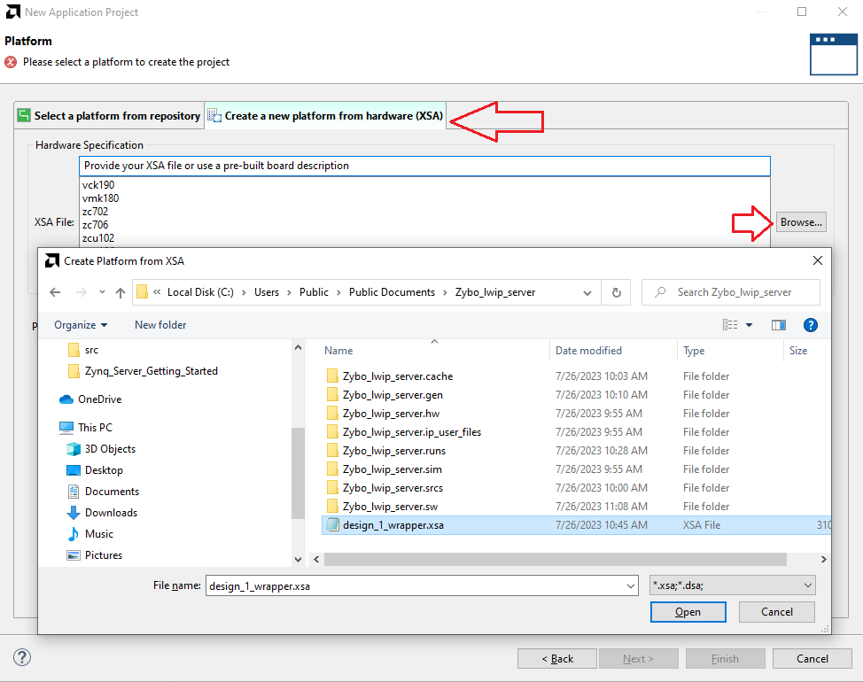
Create the project based on the HDL wrapper exported from Vivado. Browse to the Vivado folder and select the .xsa wrapper file
Click Next

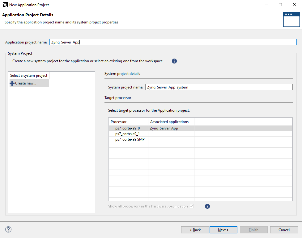
Give your new application a name. Click Next
Click Next

Next, select the type of project you wish to create - choose lwIP Echo Server to create the project and source code.
Click Finish

9. Build and Launch Echo Server
Right-mouse-click the System folder and select Build from the menu.

When the build process has been completed, start a serial terminal program, such as Putty, and connect to the board's COM port. You can use the Windows Device Manager to determine the COM port number. The Zynq processor IP includes a UART configured for 115,200 baud, 8 bits, no parity, one stop bit, and no handshaking. Configure Putty to match.

Start the echo server with the serial terminal up and running by right-mouse-clicking the Application folder. Choose RunAs→Launch Hardware(Single Application Debug)

The serial monitor should look similar to this with no errors.

10. Testing the Server With a DHCP Router
Start a second instance of Putty, specifying Telnet, to test the server.
Use the IP address and port number displayed in the serial monitor.

Test the Echo Server by typing a character. Typing a single character should display a duplicate character, confirming that the server is sending back what was typed.
11. Testing the Server Without a DHCP Router
If a router is unavailable, the echo server can be tested using a direct connection to the PC Ethernet. However, this requires a static IP setup for the PC's Ethernet port. To do this:
Open the Windows Control Panel app and select Network and Sharing Center

Find the Ethernet Connection and click it to display the status panel. It will be an unidentified network. Click Ethernet.

Click Properties.

Select Internet Protocol Version 4 (TCP/IPv4) and click Properties.

Click the Use the following IP address: bullet and type in an IP address “192.168.1.XX”, where XX is a value between 2 and 255, but not 10. This IP must not be the same as another already on your network. Click within the Subnet mask field to get the 255.255.255.0 mask to autofill. Click Ok, and you will have a static IP address.

Open Putty and enter the default IP and port number Ok.

Type anything into the telnet console and the echo server will echo back your input and display it in the console. For example, type the character Z, and the console should show ZZ. The first Z is the one you type, the Z second was echoed back by the server. Exact behavior depends on your terminal settings, like whether local echo is enabled.

When you're done experimenting with the echo server, remember to go back into Open Network and Sharing Center
Select Internet Protocol Version 4 (TCP/IPv4) and click Properties.
Select obtain an IP address automatically
Appendix: Modifying the Echo Server Code
As a simple case study in how to modify the echo server to do something else, and to better understand how the LWIP TCP API works, lets make it so that any alpha characters sent to the server to be echo'd have their case switched. So letters a-z sent to it will be echo'd as A-Z, and any letters A-Z will be returned as a-z.
First, lets trace through how a connection is handled. Rather than starting with the main file, lets look at the echo.c file. This is where the functions that the API calls are defined. To implement the desired change, we just need to look at a couple of functions:
- The
start_applicationfunction triggers when the board is booted, and initializes the server. This is our entrypoint. It registers the accept callback. - The
accept_callbackfunction triggers when a client connects to the server and makes sure data associated with the client is passed to other callbacks. It registers these other callbacks, importantly, the recv callback. - The
recv_callbackfunction triggers when data is received from a client. It then starts a write, writing back the received data. We've found the function we need to change.
Let's add a function that can perform the necessary conversion. Place it somewhere above the recv_callback function. To follow best practices, you could also add a function prototype. Here's some code that implements the case swap, without copying data:
void swap_case (char *buffer, u16 length) {
	// Swap the case of each char in the buffer in place
	for (int i = 0; i < length; i++) {
		if (buffer[i] >= 'a' && buffer[i] <= 'z') {
			buffer[i] = buffer[i] + 'A' - 'a';
		}
		else if (buffer[i] >= 'A' && buffer[i] <= 'Z') {
			buffer[i] = buffer[i] + 'a' - 'A';
		}
	}
}
Next, we need to modify the recv_callback function. To do so, we need to know a bit more about what it does and what data it has access to. Let's go over the arguments:
- The
argargument passes a pointer to data defined by a tcp_arg call. In the example, it's just a connection ID, indicating which client a packet came from. - The
tpcbargument is a pointer to a protocol control block containing a bunch of information about the connection. - The
pargument is a pointer to a packet buffer - this contains our data. - We can disregard the
errargument in this case, it indicates when something has gone wrong with the connection.
Now that we know what we have access to, let's modify the data. In the recv_callback function, somewhere between the check to see if the packet buffer is null, and the call to tcp_write that initiates the echo back, add the following code:
	/* swap the cases of alpha characters in the payload */
	swap_case(p->payload, p->len);
This function call simply invokes the function we wrote previously on the packet buffer data.
All that's left to do is to build the project and run it on your board!

Conclusion
With that, you've got an ethernet connection capable of sending data back and forth between a host computer and your FPGA development board!
For more guides on how to use your board, check out its resource center, which can be found through the Programmable Logic page of this site.