Pmod TMP3 Reference Manual
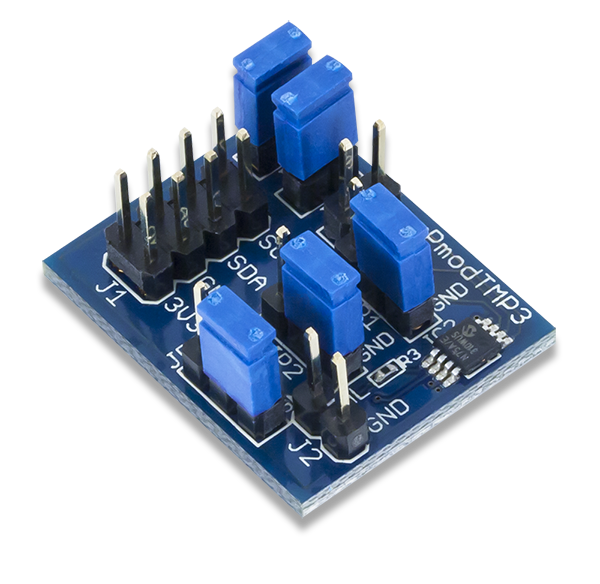
The Digilent PmodTPM3 (Revision A) is a temperature sensor module built around the Microchip TCN75A. Users may easily measure a wide range of ambient temperatures (-40°C to +125°C) at up to 0.0625 °C of resolution.
Download This Reference Manual
Features
- Ambient temperature sensor with up to 12-bit resolution
- Typical accuracy of ±1 °C
- Programmable temperature alert pin
- Multiple jumpers for eight selectable addresses
- 30 ms to 240 ms typical conversion times
- 2×4-pin port with I2C interface
Functional Description
The Pmod TMP3 utilizes theMicrochip TCN75A to provide users with up to 12 bits of resolution of ambient temperature data.
Interfacing with the Pmod
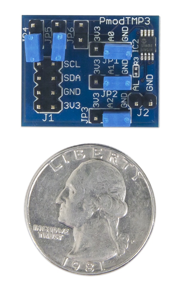
The Pmod TMP3 communicates with the host board via the I²C protocol. Users may select one of 8 different I²C slave addresses ranging from 0x48 to 0x4F by adjusting the jumpers JP1, JP2, and JP3 to either be at a digital '1' (3.3V) or a digital '0' (GND). A table explaining the different options is provided below:
| JP3 | JP2 | JP1 | Slave Address |
|---|---|---|---|
| GND | GND | GND | 0x48 (0b1001000) |
| GND | GND | 3V3 | 0x49 (0b1001001) |
| GND | 3V3 | GND | 0x4A (0b1001010) |
| GND | 3V3 | 3V3 | 0x4B (0b1001011) |
| 3V3 | GND | GND | 0x4C (0b1001100) |
| 3V3 | GND | 3V3 | 0x4D (0b1001101) |
| 3V3 | 3V3 | GND | 0x4E (0b1001110) |
| 3V3 | 3V3 | 3V3 | 0x4F (0b1001111) |
As an I²C device, the serial clock and serial data lines (SCL and SDA, respectively) need to be pulled up to the logic high voltage level through pull-up resistors. The Pmod TMP3 provides two jumper blocks, JP4, and JP5, that users can individually load to pull the two communication lines (JP4 for SDA and JP5 for SCL) up to a logic high voltage. Jumper JP6 enables a pull-up resistor to be used with the output alert pin.
To read from the Pmod TMP3 with its default settings of 9 bits of resolution, users will need to first write to the Pmod TMP3 the register address of the stored data (0x00). Users may then send a restart condition and perform a read operation from the Pmod, reading in the two bytes of information. The 9-bits of temperature data are arranged in a two's complement format, with the first 9 bits in the two bytes consisting of the temperature data and the remaining 7 bits as 0's.
A pinout table of the Pmod TMP3 is provided below:
Pinout Description Table
| Header J1 | Jumper Blocks | |||||
|---|---|---|---|---|---|---|
| Pin | Signal | Description | Jumper Block | State | Description | |
| 1 & 5 | SCL | Serial Clock | JP1 | 3V3/GND | Address bit 1 high/low | |
| 2 & 6 | SDA | Serial Data | JP2 | 3V3/GND | Address bit 2 high/low | |
| 3 & 7 | GND | Power Supply Ground | JP3 | 3V3/GND | Address bit 3 high/low | |
| 4 & 8 | 3V3 | Positive Power Supply | JP4 | Enabled | SDA pull-up enabled | |
| Header J2 | JP5 | Enabled | SCL pull-up enabled | |||
| Pin | Signal | Description | JP6 | Enabled | Alert pull-up enabled | |
| 1 | AL | Alert Pin | ||||
| 2 | GND | Power Supply Ground | ||||
Any external power applied to the Pmod must be within 2.5V and 5.5V; however, it is recommended that Pmod is operated at 3.3V.
Physical Dimensions
The pins on the pin header are spaced 100 mil apart. The PCB is 1 inch long and 0.8 inches wide.
Additional Information
The schematics of the Pmod TMP3 are available here. Additional information about the Microchip TCN75A including communication modes and specific timings of the chip can be found by checking out its datasheet here.
Example code demonstrating how to get information from the Pmod TMP3 can be found here.
If you have any questions or comments about the Pmod TMP3, feel free to post them under the appropriate section (“Add-on Boards”) of the Digilent Forum.


