Lab 4b: Application of Asynchronous Serial Communications Protocol for Real-time Control
Download This Document
1. Objectives
- To control and monitor the operations of a stepper motor using serial communications between a PIC32 microprocessor and a computer terminal.
- To implement real-time control using a preemptive foreground-background task scheduling scheme.
- Simulate an environment that provides both local and remote control of a real-time system.
2. Basic Knowledge
- Elements of ASCII text encoding.
- How to program the PIC32 processor to both generate and receive and decode serial text data.
3. Equipment List
3.1. Hardware
- Workstation computer running Windows 10 or higher, MAC OS, or Linux
In addition, we suggest the following instruments:
3.2. Software
The following programs must be installed on your development work station:
4. Project Takeaways
- Knowledge of a PC terminal emulation program.
- How to develop a library of PIC32 software to provide bi-directional communications of single characters and strings of characters.
- How to generate and decode ASCII text strings.
- How to implement a human-machine interface (HMI) using point-to-point serial communications.
5. Fundamental Concepts
Serial communication is the process of sending data one bit at a time, sequentially, over a communication channel or computer bus. This is in contrast to parallel communication, where several bits are sent as a whole on a link with several parallel channels. Both parallel and serial communications have handshaking requirements to synchronize data transfers. Although parallel communications generally have a speed advantage over serial communications, the primary advantage for serial communications is the reduced number of processor I/O pins and connecting wires or conductors.
6. Problem Statement
It requires all of the elements of software code developed and hardware used in previous labs, as well as additional hardware and software to support the serial communications with the PC. This project will require you to input text data from the serial port that will set the direction, mode, and speed of the stepper motor. This interface will be in addition to all of the controls provided in Lab 2b. The text from the serial port will be echoed to the LCD. It will be good for you to review the documentation on how the following text manipulating functions are implemented: printf, sprintf, scanf, and strcmp.
7. Background Information
Lab 4a introduced the basic concepts of UARTs and asynchronous serial communications. Lab 4b extends that knowledge by specifying a system that is capable of two independent control and monitoring locations which is common to many industrial applications, such as gantry cranes and processing plants. In this lab, the switches and push buttons on the Basys MX3, as used in lab 2b, will perform the local control functions. The Basys MX3 LCD will be used as the local display. The UART serial connection will provide the basic control and display functionality using a workstation terminal emulator program.
8. Lab 4a
8.1. Requirements
- Communications will use the PC terminal emulation program for a bit rate of 38400, even parity, 8 data bits, and one stop bit.
- Local Control Specifications of Stepper Motor
- Direction and Mode control
- BTNR controls the direction of rotor rotation of the stepper motor.
- BTND controls the stepper motor step mode.
- The speed of rotation must be the same regardless of stepper mode operation.
- The speed of rotation is set by the hexadecimal value set on the eight slide switches. SW7 is the most significant bit and SW0 is the least significant bit.
- The speed of the motor is to be displayed on the 4-digit 7-segment LED display in RPM.
- The four digits of the Basys MX3 7-segment display are continually updated with a 1 ms persistence (each digit must be turned on for 1 ms). The four digits will be lit in a round-robin fashion in a foreground operation managed by Timer 1 ISR.
- Stepper motor outputs are changed in the Timer 1 ISR using the period as determined by the slide switch settings. The period is determined by converting RPM to ms delay between steps.
- The BTNC push button controls the ON/OFF state of the LED0 in a push-on/push-off manner.
- When LED0 is changed to “ON,” print “Stepper motor under local control” on the serial monitor. Then read switches and push buttons to set the stepper motor operations and report the status of the remote serial monitor via UART 4.
- When LED0 is changed to “OFF,” print “Stepper motor under remote control.” Followed by the message “Enter data [DIR] [MODE] [###] for [DIR] = CW or CCW, [MODE] = FULL or HALF, and [###] = stepper motor speed in RPM” to the remote serial monitor via UART 4.
- Remote Control Specifications
- Any change of the stepper motor operations made by local controls must be reported to the serial terminal using the format “[DIR] [MODE] [###]” for [DIR] = “CW” or “CCW”, [MODE] = “FULL” or “HALF”, and “[###]: = stepper motor speed in RPM.”
- When the system is under remote control operation, stepper motor control is implemented using a command string in the following format: [DIR] [MODE] [###][RETURN] where the text fields are described in 2.6.2. above. The [RETURN] character is generated when the monitor “Enter” key is pressed. All command fields must contain valid text or range of numbers, otherwise the entire command is ignored and an error message is sent back to the monitor using the text “Bad entry\n\r.”
8.2. Design Phase
- Develop a data flow diagram for the software components needed for the requirements of Lab 4b.
- Schematic diagrams: Provide a block diagram of the equipment used for Lab 4b.
- Flow diagrams: Provide a complete software control flow diagram for Lab 4b.
- Develop a test plan that lists each requirement stated in section 8.1, including a column for PASS/FAIL.
8.3. Construction Phase
- Launch a new Microchip MPLAB X project called Lab4b. Add the config_bits.h file to the project.
- Add lab4b.c file to project Lab4b. The initialization segment of the main function should configure all I/O pins, initialize UART 4, initialize the Timer 2 interrupts, set LED0 on (indicating local operating mode), and set all global variables.
- Add all stepper motor files used in Lab 2b to the project.
- Add the UART functions developed for Lab 4a.
- This program will contain the function main and process the serial text. Put the following tasks inside the while(1) loop:
- Check for BTNC being pressed.
- Check if a command line of text has been entered.
- The direction and mode string variables can be decoded using the string compare function “strcmp.” An example of using this function would be:
x = strcmp(mode_txt,”FULL”);
- Only if the string of data in mode_txt is exactly equal to FULL will the value of “x” equal zero. You must include <string.h> to be able to use this function.
- After decoding the string data, set the global variables that control direction, mode, and step delay (computed from RPM setting).
8.4. Testing
- Run the project. Complete the test plan that was developed above.
9. Questions
1. Why is it appropriate that the UART getstrU4 function be a background process?
2. What are the advantages of using serial communications to link to processors?
3. What are the disadvantages of using serial communications to link to processors?
10. References
- PIC32MX330/350/370/430/450/470 Family Data Sheet
- “Using the USART in Asynchronous Mode”, http://ww1.microchip.com/downloads/en/DeviceDoc/usart.pdf
- “Asynchronous Communications with the PICmicro® USART”, http://ww1.microchip.com/downloads/en/AppNotes/00774a.pdf
Appendix A: Basys MX3 Schematic Drawings
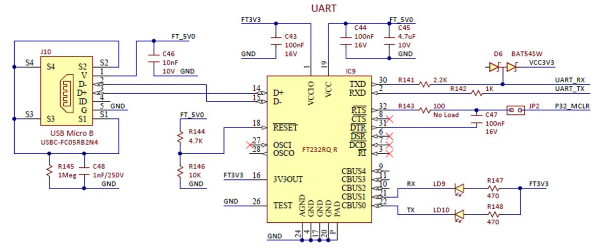 Figure A.1. PIC32MX370 to FT232RQR IC schematic diagram.
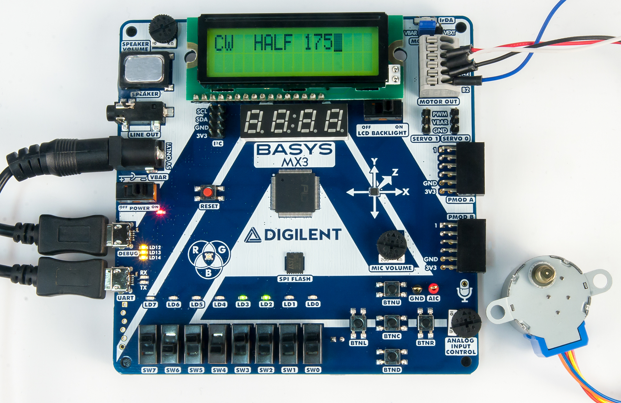 Figure A.2. LCD and switches on the Basys MX3 that controls the stepper motor speed.
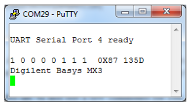 Figure A.3. PuTTy screenshot generating LCD display.
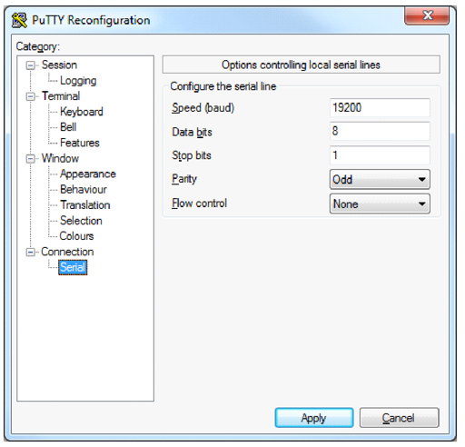 Figure A.4. PuTTY screen shot of serial configuration for 19200 BAUD and ODD parity.
Appendix B: Allocating a Heap in MPLAB X
If when compiling your project you see an error like “ld.exe Error: A heap is required, but has not been specified,” this is because you need to specify a heap size by setting “Run” →“Set Project Configuration” → “Customize…”. Go to the “xc32-ld” category (under “XC32 (Global Options)”) → “Heap size (bytes)” to “0” The configuration window should look like Fig. B.1. Click on the “Apply” button followed by clicking on the “OK” button. See http://microchip.wikidot.com/mplabx:creating-a-heap.
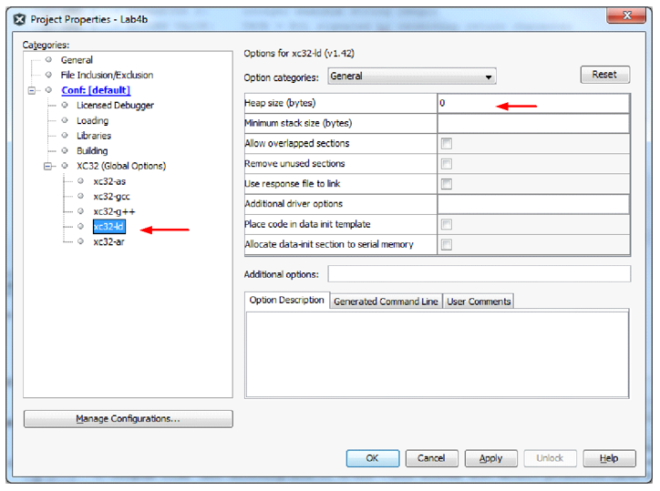 Figure B.1. Allocating Heap size.
