TechTip: Measuring Thermocouples with Raspberry Pi® and the MCC 134
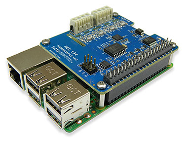
Introduction Thermocouples are a popular way to measure temperature due to their low cost, ease-of-use, and wide measurement range. Measurement Computing Corp (MCC) has a long history of designing and building accurate DAQ devices for measuring thermocouples. However, designing a device that accurately measures thermocouples in the uncontrolled environment of the Raspberry Pi was challenging. This article explains the difficulties in making accurate thermocouple measurements, how the MCC 134 DAQ HAT accomplishes it, and how MCC 134 users can minimize measurement errors.
How Thermocouples Work
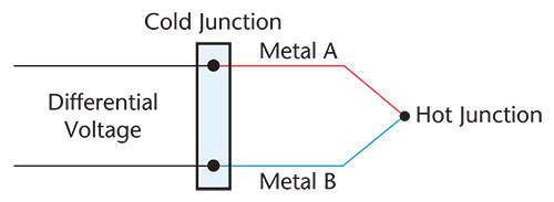
A thermocouple is a sensor used to measure temperature. It works by converting thermal gradients into electrical potential difference - a phenomenon known as the Seebeck effect. A thermocouple is made of two wires with dissimilar metals joined together at one end, creating a junction. Because two dissimilar metal wires create different electric potentials over a temperature gradient, a voltage is induced in the circuit that can be measured.
Different thermocouple types have different combinations of metal in the wires and are used to measure different temperature ranges. For example, J type thermocouples are made with iron and constantan (copper-nickel alloy) and are suited for measurements in the –210 °C to 1200 °C range, while T type thermocouples are made with copper and constantan and are suited for measurements in the –270 °C to 400 °C range.
The thermal gradient, mentioned above, is referred to as the temperature difference between the two junctions — the measurement or hot junction at the point of interest, and the reference or cold junction at the measurement device connector block.
Note: the hot junction refers to the measurement junction and not its temperature; this junction might be hotter or colder than the reference or cold junction temperature.
Thermocouple Measurement Fundamentals
Thermocouples produce a voltage relative to the temperature gradient - the difference between the hot and cold junction. The only way to determine the absolute temperature of the hot junction is to know the absolute temperature of the cold junction.
While older systems relied on ice baths to implement a known cold junction reference, modern thermocouple measurement devices use a sensor or multiple sensors to measure the terminal block (cold junction) where thermocouples connect to the measurement device.
Sources of Thermocouple Errors
Thermocouple measurement error comes from many sources, including noise, linearity and offset error, the thermocouple itself, and measurement of the reference or cold junction temperature. In modern 24-bit measurement devices, high-accuracy ADCs are used, and design practices are implemented to minimize noise, linearity and offset errors. Thermocouple error cannot be avoided but can be minimized. This error is due to the imperfections in alloys used as they vary slightly from batch to batch. Certain thermocouples inherently have less error. Standard type K and J thermocouples have up to ±2.2 °C error while type T thermocouples have up to a ±1 °C error. More expensive thermocouples (SLE - Special Limits of Error) are made with higher grade wire and can be used to reduce these errors by a factor of 2.
Accurately measuring the cold junction, where the thermocouples connect to the device, can be a challenge. In more expensive instruments like the DT MEASURpoint products, an iso-thermal metal plate is employed to keep the cold-junction consistent and easy to measure with good accuracy. In lower cost devices, isothermal metal blocks are cost prohibitive, and without an iso-thermal block it is not possible to measure the temperature at the exact point of contact between the thermocouple and the copper connector. This fact makes the cold junction temperature measurement vulnerable to temporary error driven by quickly changing temperatures or power conditions near the cold junction.
Design Challenges of the MCC 134
To better understand the design challenges of the MCC 134, let's compare it to the design of MCC's popular E-TC — a high-accuracy ethernet connected thermocouple measurement device. The cold junction temperature of the E-TC is measured by the Analog Devices ADT7310 IC temperature sensor. The IC sensor design works well in the MCC E-TC because the measurement environment is controlled and consistent. The outer plastic case controls the airflow and the electronic components and processors operate at a constant load. In controlled environment of the E-TC, the IC sensor does an excellent job of measuring the cold junction temperature accurately.
However, when the MCC 134 was first designed with an IC sensor to measure the cold junction temperature, it became apparent during the device validation process that the accuracy was insufficient. Since the IC sensor could not be placed close enough to the connector block, large and un-controlled temperature gradients caused by the Raspberry Pi and the external environment led to poor measurement repeatability.
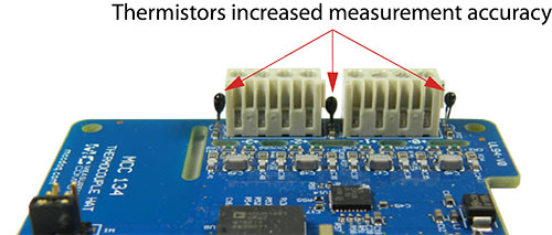
MCC redesigned the MCC 134 with an improved scheme that provides far better accuracy and repeatability while keeping the cost low. Instead of using an IC sensor and one terminal block, MCC redesigned board with two terminal blocks and three thermistors — one placed on either side and in between of the terminal blocks (shown below). Although this added complexity to the design, the thermistors more accurately tracked the temperature changes of the cold junction, even during changes in processor load and environmental temperature.
This design yields excellent results that are far less susceptible to the uncontrolled Raspberry Pi environment. Even with this new design, however, certain factors affect accuracy, and users can improve their measurement results by reducing quick changes in temperature gradients across the MCC 134.
Best practices for accurate thermocouple measurements using the MCC 134
The MCC 134 should achieve results within the maximum thermocouple accuracy specifications when operating within the documented environmental conditions. Operating in conditions with excessive temperature transients or airflow may affect results. In most cases, the MCC 134 will achieve the typical specifications. In order to achieve the most accurate thermocouple readings, MCC recommends the following practices:
- Reduce the load on the Raspberry Pi processor. Running a program that fully loads all 4 cores on the Raspberry Pi processor can raise the temperature of the processor above 70 °C. Running a program that only loads 1 core will operate approximately 20 °C cooler.
- Minimize environmental temperature variations. Place the MCC 134 away from heat or cooling sources that cycle on and off. Sudden environmental changes may lead to increased errors.
- Provide a steady airflow, such as from a fan. A steady airflow can dissipate heat and reduce errors.
- When configuring multiple MCC DAQ Hats in a stack, position the MCC 134 farthest from the Raspberry Pi board. Since the Raspberry Pi is a significant heat source, placing the MCC 134 farthest from the Pi will increase accuracy.
Conclusion
Thermocouples provide a low-cost and flexible way to measure temperature, but measuring thermocouples accurately is difficult. Through innovative design and extensive testing, MCC overcame the challenge of measuring thermocouples accurately in the uncontrolled Raspberry Pi environment. The MCC 134 DAQ HAT provides the ability to use standard thermocouples with the fast growing, low-cost computing platform.
More Information
Please reach out to our support team on the Digilent Forum if you have any questions: https://forum.digilent.com/
Additional TechTips are available here in Digilent Reference: App Notes, Tech Tips, and Other Documents


