This is an old revision of the document!
Basys3 XADC Demo
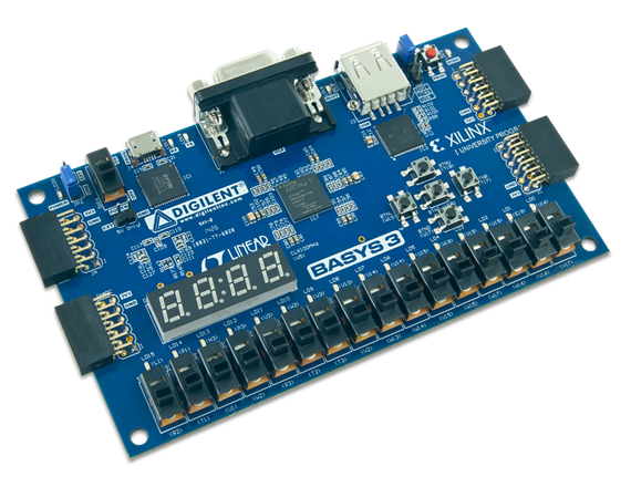
Features Used
| Not Used | Used | |
|---|---|---|
| 16 User Switches | X | |
| 16 User LEDs | X | |
| 5 User Push Buttons | X | |
| 4-digit 7-Segment Display | X | |
| 4 Pmod Connectors | X | |
| XADC Analog Input | X | |
| 12-bit VGA Output | X | |
| USB-UART Bridge | X | |
| Serial Flash for Application Data | X | |
| USB HID Host With Mouse | X | |
| USB HID Host With Keyboard | X |
Description
This simple XADC Demo project demonstrates a simple usage of the Basys3's XADC port capability. The behavior is as follows:
- The 16 User LEDs increment from right to left as the voltage difference on the selected XADC pins gets larger.
- The two seven segment displays show the voltage difference on the AD6, AD7, AD14, AD15 pins in volts.
- sw0 and sw1 select which channel to read from
How to Build and Program
You will need…
1. Vivado installed on your computer
2. Nexys4-DDR board from digilent
3. Wires and a voltage to measure
1. Download the Project
Download the project zip file here. basys3xadc.zip Once you have downloaded the project, unzip it in the location of your choosing.
2. Load the Vivado Project
In your now unzipped project, open the file basys3XADC.xpr. This should open your project in Vivado.

3. Synthesize, Implement and Generate Bitstream
To complete this step all that you need to do is click Generate Bitstream on the left hand menu towards the bottom. Vivado will run through both Run Synthesis and Run Implementation before it generates the bitstream automatically. If you want, you can click each step by itself in the order of Run Synthesis, Run Implementation and then Generate Bitstream.

4. Connect and Program the Basys3
Once you have generated your bit file, Click on the hardware manager and connect to your board by choosing the local server option.

After your board is connected, just click program to load the XADC demo onto your Basys3.
Running the Basys3 GPIO Demo
To run all the features of this demo, you will need the Basys3 board, a monitor with a VGA cable and a USB mouse.
1. Using the Switches with Leds
For this section, all the switches are tied to their corresponding led. Every time a switch is toggled, the led directly above it will toggle with it.


2. Using the buttons with The Seven Segment Display
The seven segment display is counting all digits from 0 to 9 when no buttons are pressed. If BTNU is pressed, the first digit on the seven segment display is blacked out. BTNL blacks out the second digit, BTNR blacks out the third, and BTND eliminates the fourth. BTNC blacks out all the digits.


3. Plugging in a monitor to the VGA port
To use the VGA output demo, plug in your monitor to the Basys3 VGA port. The monitor screen will have series of moving patterns as seen below.

4. Plugging in and using a USB mouse
To see the USB mouse portion of the demo, plug a USB mouse into J2 on the Basys3 with the monitor still connected. On the screen, you should be able to see your mouse pointer and move it around.
5. UART Communication
To see the UART communication channel, open a terminal program on your computer set to 9600 baud, 8 data bits, no parity bit and 1 stop bit. On reset or BTNC, the Basys3 will print BASYS3 GPIO/UART DEMO! to the terminal. On a button press other than BTNC, the terminal will print Button press detected!
