Despite our hopes and effort to create an innovative and low-cost T&M solution, we’ve received consistent negative feedback on the OpenScope MZ and OpenLogger regarding overall reliability that has led us to determine that it is not up to our high standards for our test and measurement products.
Unfortunately, we are unable to fix many of the issues, so we have made the difficult decision to pull both products, and related accessories from our shelves. This will allow us to ensure we can continue to deliver on the Digilent brand promise and focus our efforts on expanding our popular and core line of Test and Measurement Products.
The materials on this page will remain here as legacy sources. Any Digilent provided support for this material will be extremely limited at best. Thank you for understanding.
OpenLogger Reference Manual
OpenLogger is a wireless data logging and data acquisition device that can be controlled via USB or WiFi. Using a computer or mobile device, signals from circuits and sensors can be acquired, stored, analyzed, visualized, and generated. OpenLogger makes it easy to monitor multiple analog inputs and simultaneously log the data to an SD card, and/or stream over USB or WiFi, all through WaveForms Live.


Features
- Connectivity
- ATWINC1500 WiFi chip (802.11n)
- USB 2.0 (High Speed Required)
- Analog Inputs
- 8 Channels
- 12-bit resolution per channel
- 500 kS/s sample rate
- 50 kHz of bandwidth at -3dB
- 1 MΩ of input impedance
- ±10 V input voltage range
- Maximum buffer size of 32640 samples per channel
- Function Generator
- 1 Channel
- Sine, triangle, sawtooth, square and DC outputs
- 10-bit resolution
- 2 MS/s sample rate
- 3 V pk2pk output with ±1.5 V offset
- 10 mA output current
- 25000 sample buffer size
- Logic Analyzer and GPIO
- 10 Channels multiplexed between the Logic Analyzer and as general purpose IO
- 3.3V CMOS logic for both the Logic Analyzer and GPIO
- 7 mA source and 12 mA sink when used as GPIO
- Logic Analyzer has a sample rate of 10 MS/s
- Maximum buffer size of 32640 samples per channel for the Logic Analyzer
- Power Supply
- 2 Channels
- ±4 V output voltage
- 50 mA per channel
- Other features
- USB powered device
- 4 user LEDs
OpenLogger Pinout

| OpenLogger J1 Header Pinout | |||||
|---|---|---|---|---|---|
| Top Row | Bottom Row | ||||
| Pinout# | Pin Name | Pin Description | Pinout# | Pin Name | Pin Description |
| 1+ | AI1 | Analog Input 1 | ⇓ | AGND1 | Analog Ground |
| 2+ | AI2 | Analog Input 2 | ⇓ | AGND2 | Analog Ground |
| 3+ | AI3 | Analog Input 3 | ⇓ | AGND3 | Analog Ground |
| 4+ | AI4 | Analog Input 4 | ⇓ | AGND4 | Analog Ground |
| 5+ | AI5 | Analog Input 5 | ⇓ | AGND5 | Analog Ground |
| 6+ | AI6 | Analog Input 6 | ⇓ | AGND6 | Analog Ground |
| 7+ | AI7 | Analog Input 7 | ⇓ | AGND7 | Analog Ground |
| 8+ | AI8 | Analog Input 8 | ⇓ | AGND8 | Analog Ground |
| 5V | 5V | 5V Supply | ↓ | GND | Digital Ground |
| R | RST | Button Reset | P | PROG | Button Program |
| TI | Tin | Reserved | TO | Tout | Reserved |
| W1 | AWG | Function Generator Output | ↓ | GND | Digital Ground |
| V1 | DC1 | DC Out 1 | ↓ | GND | Digital Ground |
| V2 | DC2 | DC Out 2 | ↓ | GND | Digital Ground |
| D0 | DIO0 | Digital IO 0 | D4 | DIO4 | Digital IO 4 |
| D1 | DIO1 | Digital IO 1 | D5 | DIO5 | Digital IO 5 |
| D2 | DIO2 | Digital IO 2 | D6 | DIO6 | Digital IO 6 |
| D3 | DIO3 | Digital IO 3 | D7 | DIO7 | Digital IO 7 |
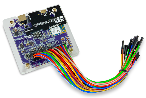
Walk Around the Board
")
Software Support
The Digilent Agent and WaveForms Live are used to configure and communicate with the OpenLogger, as well as for viewing captured data. More information can be found on their respective Resource Centers, linked above, as well as the OpenLogger Resource Center.
Important!
The OpenLogger can only be used with Windows operating systems.
Analog Inputs
Analog inputs provide ways to measure real analog data from external systems. OpenLogger has 8 single-ended analog inputs with their own recommended ground pin. Each input is designed to accept a voltage range of -10 V to +10 V (with protection up to ±30 V) and has 12 bits of resolution and a bandwidth of 50 kHz. OpenLogger can then log all data onto the local SD card at 500 kS/s, stream and/or log data over USB at 500 kS/s, or stream and/or log data over WiFi at 10 kS/S.
The analog inputs has the following features:
- 8 Channels
- 12 bits of resolution per channel
- 500 kS/s aggregate input
- 50 kHz bandwidth at -3 dB
Information on how to use the OpenLogger's Analog Inputs can be found in the OpenLogger's Data Logger tutorial.

Function Generator
The OpenLogger has a single channel 2 MS/s, 10-bit function generator. An R2R resistor ladder with 1% resistors is used in place of a DAC.
The function generator supports:
- Sine, triangle, sawtooth, square and DC outputs
- 10-bit resolution
- 1 Hz to 200 kHz frequency
- 3 V pk2pk output with ±1.5 V offset
- 20 mA output current
Information on how to use the OpenLogger's Function Generator can be found in the OpenLogger's Function Generator tutorial.

Digital I/O
Digital I/O provide generic inputs and outputs to detect and provide ways to detect and provide high and low logic states. The OpenLogger has 8 user IO pins that are available for general use.
Information on how to use the OpenLogger's Digital I/O can be found in the OpenLogger's Digital I/O tutorial.

DC Power Supplies
OpenLogger has two DC outputs that are driven by their own PWM output with a single PWM line for the DC offset. A gain circuit is implmented on the OpenLogger to provide a voltage range of -4 V to 4 V for each channel. A feedback circuit is also present to allow for calibration of the DC output.
- 2 channels
- ±4 V
- 50 mA per channel
Information on how to use the OpenLogger's Power Supplies can be found in the OpenLogger's Power Supplies tutorial.

Troubleshooting
LED Indicators
The LEDs on the OpenLogger are used to indicate the current status of the OpenLogger hardware as follows:
- Orange On - Device is booting and not ready to use.
- Green Flashing - Device is booted and ready to use, but not logging.
- Green Solid - Device is logging to the RAM buffer and streaming is currently available.
- Green and Orange Solid - Device is both logging and streaming.
- Green Solid and Orange Flashing - Device is streaming to the RAM buffer, but logging to the SD card or through Wifi has stopped
- For the SD card, this usually indicates there is no more space on the SD card
- Red Solid - One of the internal buffers was overrun
- Filling the SD card does not cause an overrun condition
- Red Flashing - Warning that the device is falling behind with keeping the buffers cleared
- Blue Solid - Reserved for WiFi (not yet implemented)
- Red blinking and Orange Solid - Device firmware updating
- All user LEDs Solid - An error has occurred. Reboot the OpenLogger and report the error on the Digilent Forum.