Power Measurement with the Analog Discovery Pro (ADP3450/ADP3250)
Overview
This demo uses the Analog Discovery Pro's Oscilloscope to measure the power of an RC circuit. Because the oscilloscope only measures voltages, a sensing resistor is used with the Oscilloscope's Math channels to calculate the current passing through the circuit and further the power of each component.
Inventory
- Analog Discovery Pro with:
- 3 BNC oscilloscope probes
- A BNC to minigrabber clip cable
- Analog parts and wires (found in the Analog Parts Kit):
- A 470 Ω resistor
- A 4.7 nF capacitor
- A 1 Ω resistor (sensing resistor)
- A breadboard
- WaveForms Installation, version 3.15.18 or later
Demo Setup
Hardware Setup
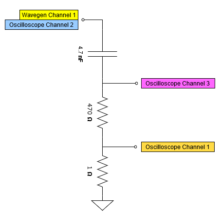
Assemble the circuit under test shown in the image to the right and connect the Oscilloscope probes and Wavegen grippers at the labeled nodes. Because the BNC probes are single-ended and don't support differential voltage measuring, care must be taken to ensure each probe ground clip is connected to the ground of the circuit.
This demo assumes the analog parts listed in the inventory are the ones being used, but it can be recreated with components of different values with adjustments made to the windowing and Math functions. Note that the sensing resistor needs to be small enough to have minimal impact on the behavior of the overall circuit.
Software Setup
Open the Wavegen instrument, configuring it to output a 5 V, 20 kHz Sine wave as shown in the image to the right.
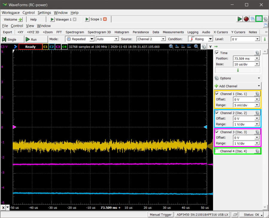
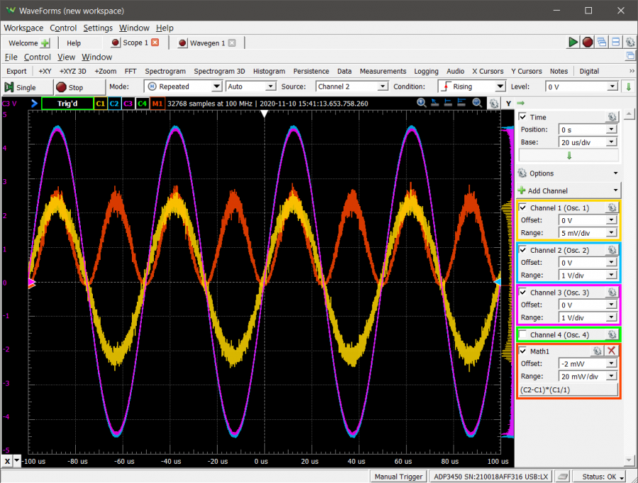
Open the Scope instrument. Enable Channels 1, 2, and 3 and adjust the ranges to match the image to the right. Adjust the ranges of each channel to 5 mV/div, 1 V/div, and 1 V/div respectively, and the base time division to 10 us/div.
Clicking the “Docking Windows” button in the upper right on WaveForms will cause WaveForms to show the Wavegen and Scope instruments in the same window. This is useful in contexts where multiple instruments will be used in quick & repeated succession.
Without leaving the Scope instrument, Run All Instruments by clicking the button in the upper right corner of WaveForms, which will start the Wavegen and the Scope instruments at the same time.
What should be seen at this stage, is the voltage drop across the sensing resistor (Ch 1), the voltage drop across the entire circuit (Ch 2), and the voltage drop across the two resistors (Ch 3), as seen in the image to the right. The current across each component can be calculated using the Scope's Math Channels, which conveniently plots the calculation alongside the voltage measurements. These next steps detail how to set them up.
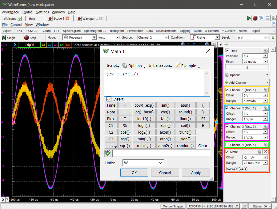
Because oscilloscopes only measure voltage, some work needs to be done in order to measure power. The Scope's Math channels can be used to perform calculations which then are plotted alongside each channel's measurements. To calculate the total power of the RC circuit, the voltage across the sensing resistor (Channel 1) is subtracted from the voltage across the entire circuit (Channel 2), and the result is multiplied by the current passing through the circuit. The current is found by dividing the voltage across the sensing resistor by its resistance, and that result is multiplied against the voltage across the RC components.
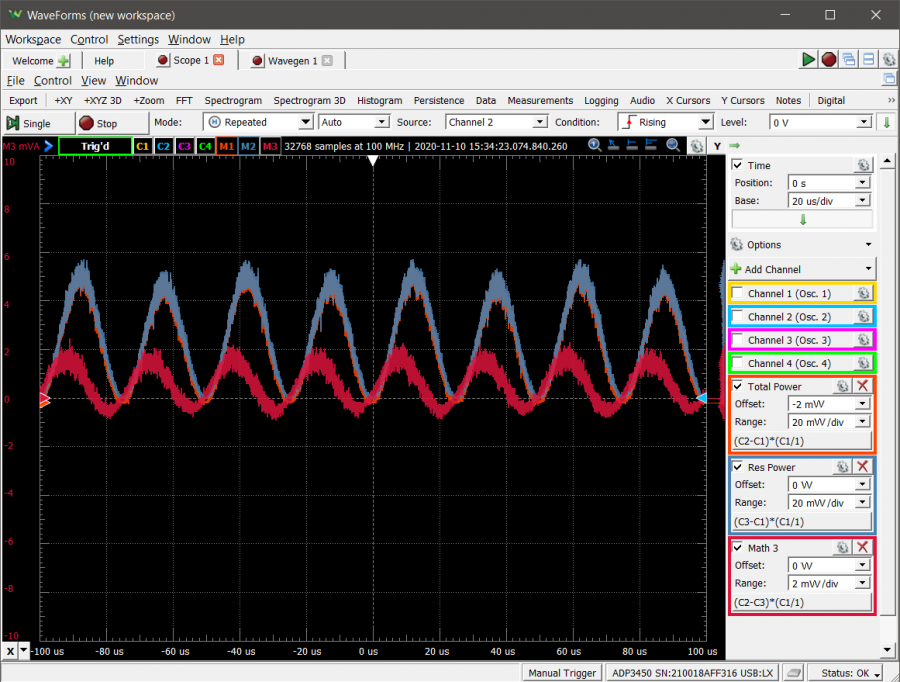
To add a math channel, click “Add Channel” dropdown menu above the oscilloscope channels and select “Custom” under the Math menu. In the new window, enter “(C2-C1)*C1/Rs”, where Rs is the resistance value of your current sensing resistor. In the script entry, set the units to “W”, and click “OK”. Adjust the range of the Math channel to 20 mW/div to better view the signal. This Math channel is plotting the total power of the circuit.
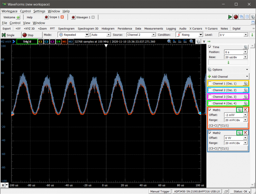
The power across the resistor can be calculated as well. To do so, the voltage across the sensing resistor is subtracted from the voltage across both resistors (Channel 3), and the result multiplied by the current passing through the resistor.
Add another Math channel, this time with the calculation of “(C3-C1)*C1/Rs”. If the chart is too cluttered with signals, click the checkmarks in the upper left of the 3 Scope channels to stop them from being plotted. Set the units to “W” and adjust the range of this channel to 20 mW/div to view the power of the resistor component of the circuit. Select Math1 and then drag the red triangle on the left of the chart down to offset the channel from Math2, since they largely overlap.
Note: Scope measurement and math channels can be renamed and relabeled in order to clarify what they represent. This can be done by expanding the channel options (the gear icon) and editing the Name and Label properties of the channel.
The capacitor power can also be calculated, by subtracting the voltage across both resistors from the total voltage across the circuit and multiplying the result by the current passing through the circuit.
Add one last Math channel with the calculation “(C2 - C3)*C1/Rs”, set the units to “W” and adjusting the range accordingly (1 mW/div). This Math channel shows the power of the capacitor component of the circuit.
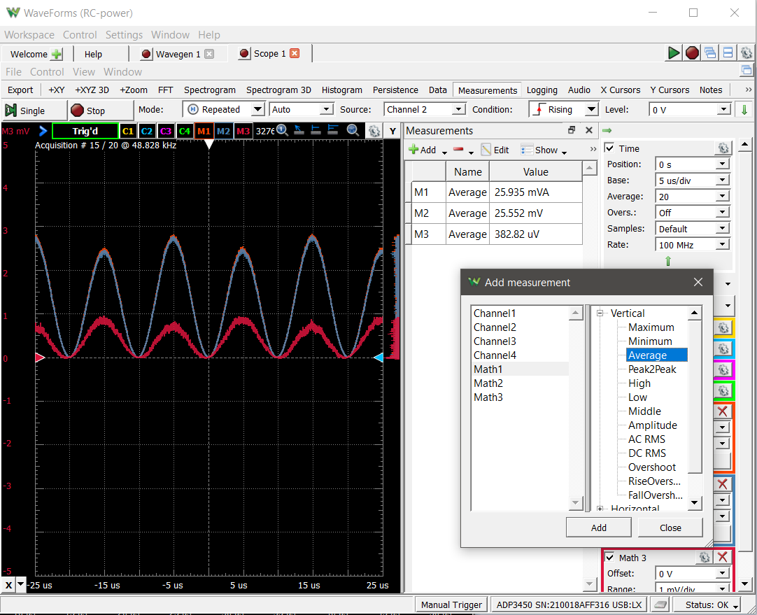
Math3 is noisy but by averaging the signals across multiple measurements this can be reduced. To do so, expand the “Advanced Options” underneath the Time base and select 10 from the Average dropdown.
To see the average value of each power measurement, click “View” in the top toolbar, then “Measurements”. In the Measurements panel, click the “Add” button then “Defined Measurement”. Select Math1 in the left panel, expand Vertical in the right then click Average. Click “Add”, then repeat for Math2 and Math3. Once done, click “Close”.
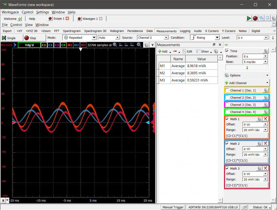
In the Wavegen, adjust the frequency of the Sine to 50 Hz, adjust the time base of the Scope instrument to 5 ms/div to accommodate the frequency change. Note the changes in the averages in the Measurements panel.
Other Resources
For more guides and example projects for your Analog Discovery Pro, please visit its Resource Center.
For technical support, please visit the Digilent Forums.

