Pmod IOXP Reference Manual
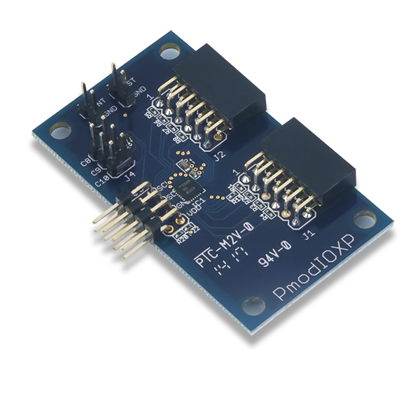
The Digilent Pmod IOXP (Revision A) is an Input/Output Expansion module capable of providing up to 19 additional IO pins.
Download This Reference Manual
Features
- Communicates via the I²C interface
- 16-element FIFO for event recording
- 19 configurable I/Os
- Built-in keypad decoding for matrices up to 11×8
- PWM generator
- Open-drain interrupt output
- Two programmable logic blocks
- Debouncing on IOs
Functional Description
The Pmod IOXP utilizes Analog Devices' ADP5589. Through the use of I²C, users may expand from the two I/O pins required to nearly 10 times the amount of available I/O.
Interfacing with the Pmod
The Pmod IOXP communicates with the host board via the I²C protocol. By sending out the 7-bit slave address of 0110100 and a read or write bit (1/0), users may then read or write to a specific register to configure the Pmod to enable interrupts or read the status of GPIO pins.
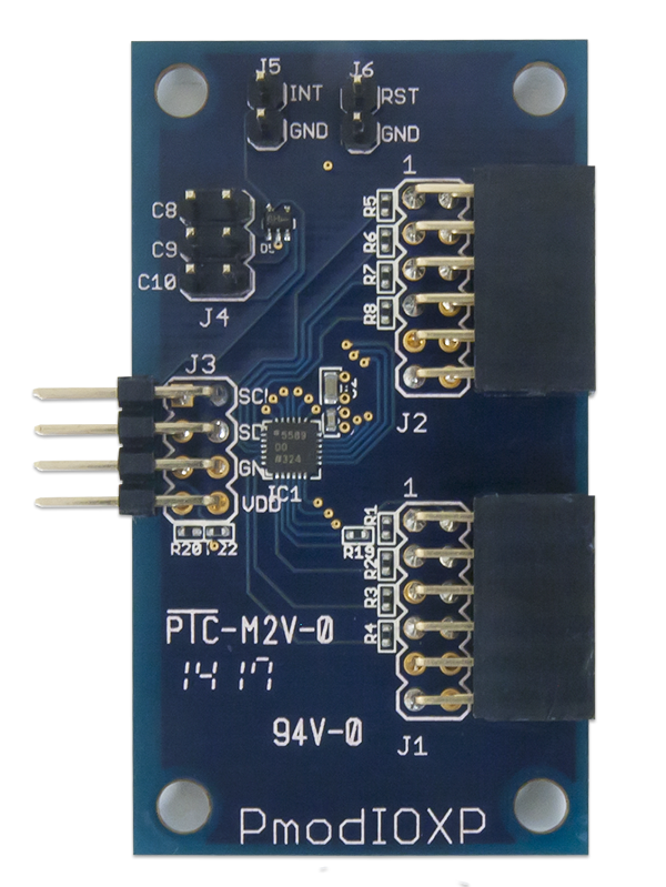
Pinout Description Table
| Header J3 | Header J1 | ||||||||
|---|---|---|---|---|---|---|---|---|---|
| Pin | Signal | Description | Pin | Signal | Description | Pin | Signal | Description | |
| 1 & 5 | SCL | Serial Clock | 1 | R0 | GPIO 1 or Row 0 for keypad mode | 7 | C0 | GPIO 9 or Column 0 for keypad mode | |
| 2 & 6 | SDA | Serial Data | 2 | R1 | GPIO 2 or Row 1 for keypad mode | 8 | C1 | GPIO 10 or Column 1 for keypad mode | |
| 3 & 7 | GND | Power Supply Ground | 3 | R2 | GPIO 3 or Row 2 for keypad mode | 9 | C2 | GPIO 11 or Column 2 for keypad mode | |
| 4 & 8 | VCC | Power Supply (3.3V) | 4 | R3 | GPIO 4 or Row 3 for keypad mode | 10 | C3 | GPIO 12 or Column 3 for keypad mode | |
| 5 | GND | Power Supply Ground | 11 | GND | Power Supply Ground | ||||
| 6 | VCC | Positive Power Supply | 12 | VCC | Positive Power Supply | ||||
| Header J4 | Header J2 | ||||||||
|---|---|---|---|---|---|---|---|---|---|
| Pin | Signal | Description | Pin | Signal | Description | Pin | Signal | Description | |
| 1 | C8 | GPIO 17 or Column 8 for keypad mode | 1 | R4 | GPIO 5 or Row 4 for keypad mode | 7 | C4 | GPIO 13 or Column 4 for keypad mode | |
| 3 | C9 | GPIO 18 or Column 9 for keypad mode | 2 | R5 | GPIO 6 or Row 5 for keypad mode | 8 | C5 | GPIO 14 or Column 5 for keypad mode | |
| 5 | C10 | GPIO 19 or Column 10 for keypad mode | 3 | R6 | GPIO 7 or Row 6 for keypad mode | 9 | C6 | GPIO 15 or Column 6 for keypad mode | |
| 2 & 4 & 6 | GND | Power Supply Ground | 4 | R7 | GPIO 8 or Row 7 for keypad mode | 10 | C7 | GPIO 16 or Column 7 for keypad mode | |
| 5 | GND | Power Supply Ground | 11 | GND | Power Supply Ground | ||||
| 6 | VCC | Positive Power Supply | 12 | VCC | Positive Power Supply | ||||
| Header J5 | Header J6 | |||||
|---|---|---|---|---|---|---|
| Pin | Signal | Description | Pin | Signal | Description | |
| 1 | ~INT | Active low interrupt output | 1 | ~RST | Active low reset input | |
| 2 | GND | Power Supply Ground | 2 | GND | Power Supply Ground | |
Any external power applied to the Pmod IOXP must be within 1.65V and 3.6V; it is recommended that Pmod is operated at 3.3V.
Physical Dimensions
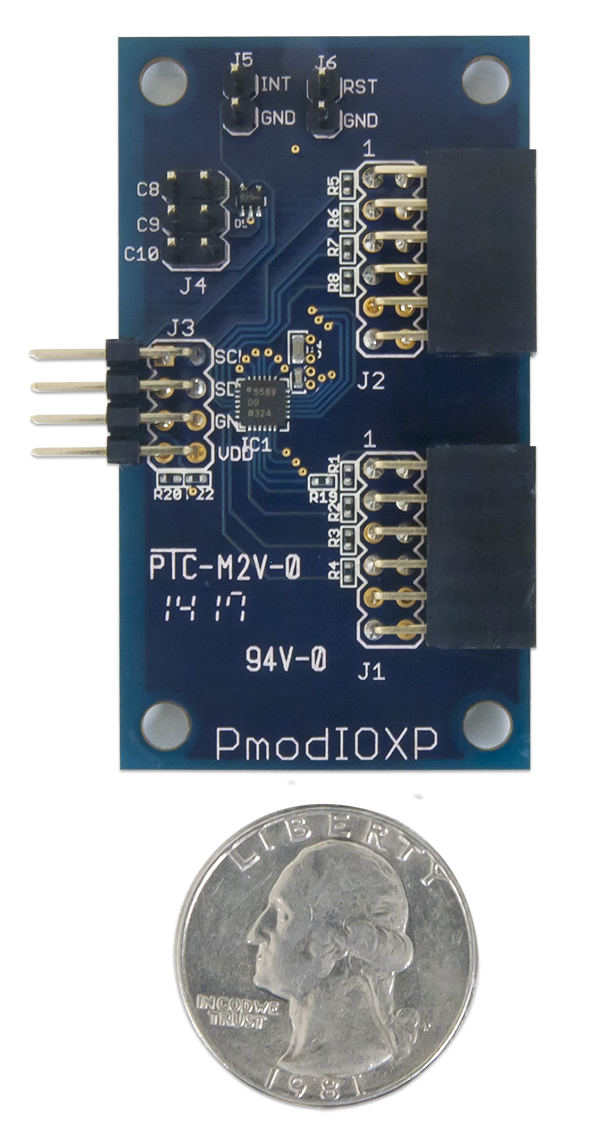
The pins on the pin header are spaced 100 mil apart. The PCB is 1.3 inches long on the sides parallel to the pins on the pin header and 2.3 inches long on the sides perpendicular to the pin header.
Additional Information
The schematics of the Pmod IOXP are available here. Additional information about the I/O expansion module including communication modes and specific timings of the chip can be found by checking out its datasheet here.
More specific information about how to use the Pmod IOXP can be found by checking out our user guide. Example code demonstrating how to get information from the Pmod IOXP can be found here.
If you have any questions or comments about the Pmod IOXP, feel free to post them under the appropriate section (“Add-on Boards”) of the Digilent Forum.


