This is an old revision of the document!
Using Github Demos
Overview
Digilent provides several projects through Github that are designed to demonstrate different uses of our FPGA and Zynq boards. This guide will describe how to download and use these projects.
At the end of this tutorial you will have your demo project running on your board.
Prerequisites
Hardware
- A Supported Digilent 7-Series FPGA or Zynq Board
- USB Cables
Software
- Xilinx Vivado 2016.X
- Vivado 2016.4 is used in this tutorial
- Digilent Board Support Files
- Follow the wiki guide on how to install Board Support Files for Vivado 2015.X
- Projects Supported by this Tutorial
-
Platform Project Name Uses SDK Hardware Handoff Available Wiki Link Github Link Arty Pmod VGA Demo No No Internal Link External Link
Important
For further requirements, please review the project's wiki page .
Tutorial
1. Download the Project ZIP from the Digilent Github
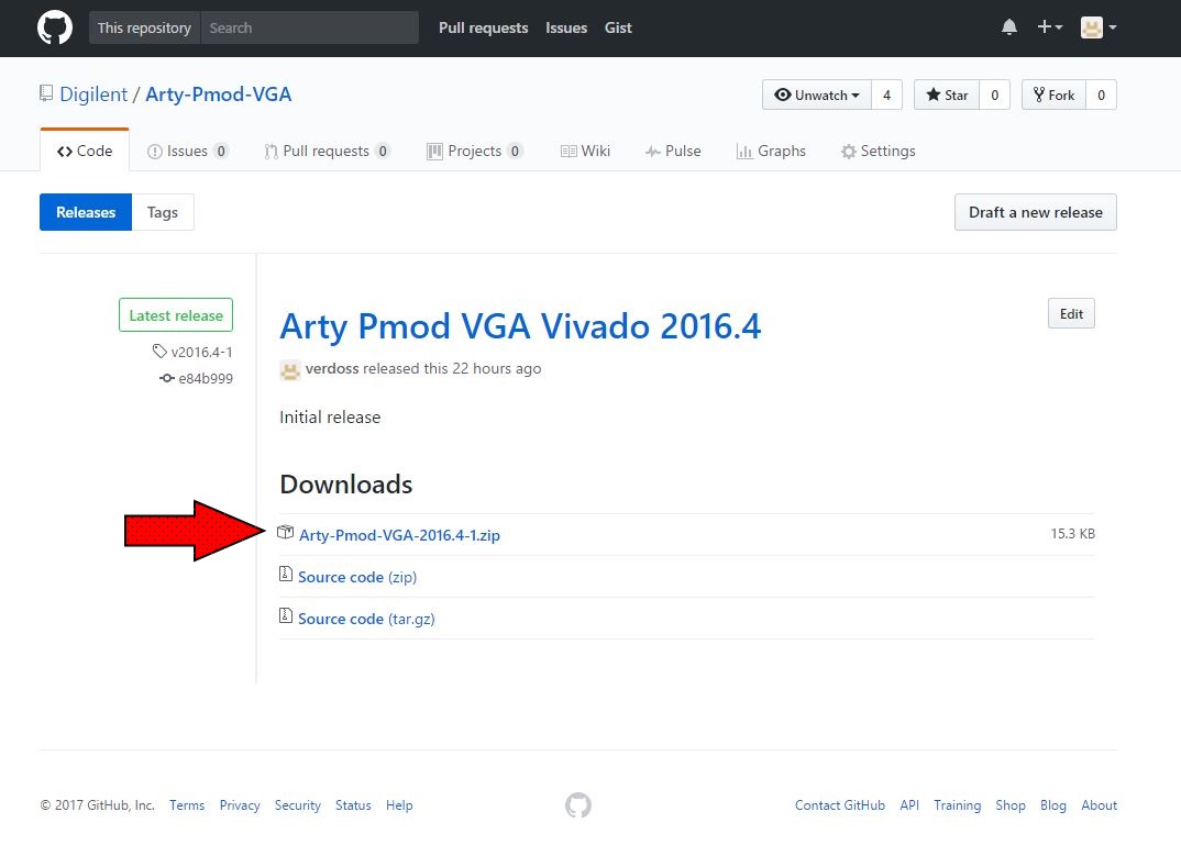
1.1) From the demo repository landing page, select the release link.

1.2) If the repository has multiple releases, select Latest Release, then click on the project ZIP file included in the Downloads section of the release to download it.
Important
Make sure that you download the project-2016.4-x.zip, not the source code archive.

1.3) All of the necessary files are included within each project folder, with relative file paths established, so as long as the files aren't moved around within the folder, you can move and run the project from any location.
2. Find the Location of the Tcl Script
Within the project folder there will be several subfolders named “hw_handoff”, “proj”, “src”, “repo”, and “sdk”. Go into the proj folder, right click the “create_project” file and select Properties. Highlight and copy the file's location.

3. Create the Project in Vivado
3.1) Open Vivado and find the Tcl Console on the bottom of the window. Enter the letters 'cd' (change directory) followed by the file path you copied earlier.
Important
Select the proj folder from the drop-down menu to make sure that Vivado converts the path's back slashes ' / ' to forward slashes ' \ '. Vivado will not recognize the path otherwise.


3.2) Enter the command “source ./create_project.tcl”, this will set up the project for you within the proj directory you previously cd'd into.

3.3) The project will now be open in Vivado and you can navigate through the Design Sources subwindow or select Open Block Design in the project flow manager to the left to see how the project hardware works. (Not all projects will have a block design)
4. Program and Run the Project
The remainder of this tutorial heavily depends on the type of project you are using. If your project does not use SDK, select the HDL Only option. If your project has a hardware handoff file and you don't wish to eventually make changes to the hardware design, select the SDK Hardware Handoff option. Otherwise, select the SDK and Block Design option.
- HDL Only
-
4.1) Click Generate Bitstream on the left hand menu towards the bottom. In the “Launch Runs” dialog, make sure Launch runs on local host is selected and click OK. In the “No Implementation Results Available” dialog, click Yes to run synthesis and implementation.
Tip
If your computer has multiple cores, you can increase the number of jobs to make this process faster.
 4.2) When this process has finished, which may take a while, in the “Bitstream Generation Completed” dialog, select Open Hardware Manager and click OK. Other interesting options here include “Open Implemented Design” which will show how your project logic will be placed on the FPGA. “View Reports” will show a number of different statistics about your project, including how well it meets timing requirements and what resources of your board will be used.
 4.3) After the last step, if you don't have the hardware manager opened, select Hardware Manager from the Program and Debug section of the Flow Navigator to the left, just underneath Generate Bitstream.4.4) Select Open Target from the green bar at the top. In the drop down menu that this creates, select Open New Target.
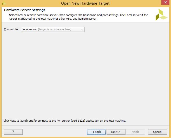
 4.5) Click Next. Then make sure that Local server is selected in the “Connect to” drop down. Connect your board to your computer with a JTAG USB cable, then click Next.
 4.6) Click Next and click Finish.
 4.7) Select Program Device from the green bar, then select your device from the dropdown list (there will usually only be one device listed). Then click Program.
Important
If nothing shows up in the “Bitstream file” text box, click the … button to the right, navigate to “proj/*.runs/impl_1” subdirectory of your project and select the “*.bit” file.


- SDK Hardware Handoff
-
4.1) Export Hardware - Include Bitsream4.2) Launch SDK4.3) Compile4.4) Import?4.5) Build All4.6) Make sure that your board is turned on and connected to the host PC via both the JTAG USB port and the UART USB port.4.7) On the top toolbar, click the Program FPGA button.4.8) Click Program to program your FPGA with your hardware design.4.9) Select your Pmods project and click the Run As… button. Select Launch on Hardware (System Debugger) and click OK.
- SDK and Block Design