This is an old revision of the document!
Zybo Z7 Pmod VGA Demo
Overview
Features Used
| Not Used | Used | |
|---|---|---|
| 4 User Switches | X | |
| 4 User LEDs | X | |
| 4 User RGB LEDSs | X | |
| 4 User Push Buttons | X | |
| 4 Pmod Connectors | X | |
| XADC Analog Input | X | |
| USB-UART Bridge | X | |
| Serial Flash for Application Data | X |
Features Used
| Not Used | Used | |
|---|---|---|
| 4 slide switches | X | |
| 5 LEDs | X | |
| 2 RGB LEDs (1*) | X | |
| 6 push buttons | X | |
| USB-UART Bridge | X | |
| Micro SD card connector | X | |
| HDMI Sink | X | |
| HDMI Source | X | |
| Pcam camera connector | X | |
| Audio codec w/ three 3.5mm jacks | X | |
| User EEPROM | X | |
| 10/100/1000 Ethernet PHY | X | |
| 1GB 1066MHz DDR3 Memory | X | |
| Serial Flash | X | |
| 6 Pmod ports (5*) | X | |
| Pmod for differential analog signals | X | |
| USB HID Host | X |
*The -7010 variant has several differences that are shown in parenthesis above
Description
This simple VGA Demo project demonstrates usage of a Pmod VGA connected to the Zybo Z7's Pmod ports. The behavior is as follows:
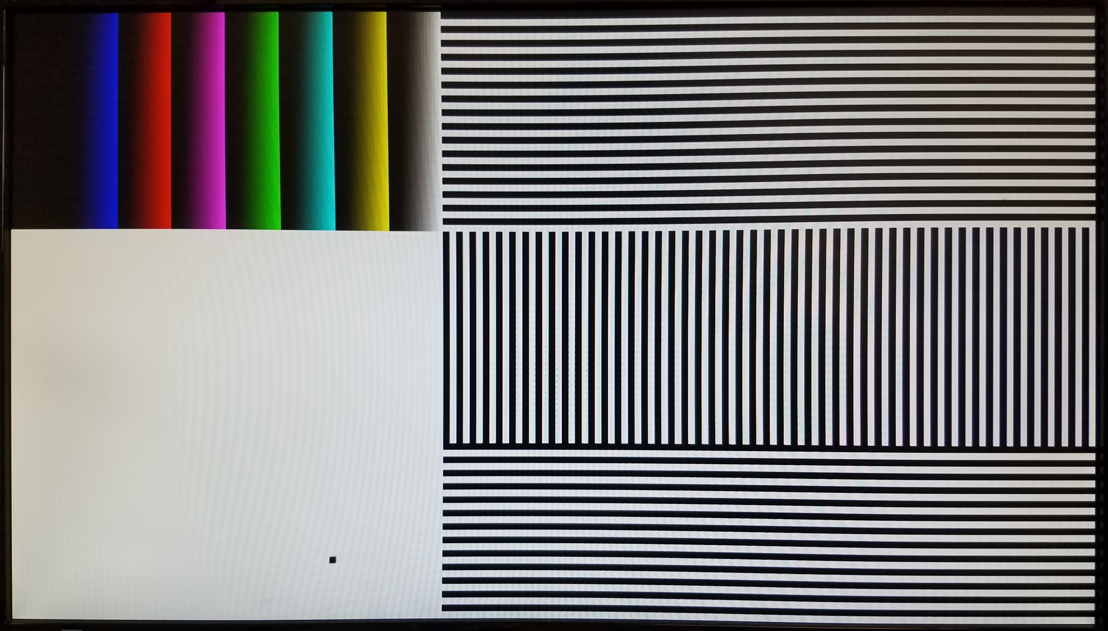
- A bouncing box and black, white, and multiple colors of bars are displayed on a connected VGA monitor.
- The Pmod VGA is controlled by the Zybo Z7 through Pmod ports JB and JC.
- The screen resolution is configurable through HDL code.
Prerequisites
Hardware
- Zybo Z7 Zynq board
- Pmod VGA
- Micro-USB cable
- VGA monitor and cable
Software
- Vivado Design Suite 2016.4
- Newer versions can be used, but the procedure may vary slightly
Downloads
Zybo Z7-10 Pmod VGA Project Repository – ZIP Archive GIT Repo
Zybo Z7-20 Pmod VGA Project Repository – ZIP Archive GIT Repo
Download and Launch the Zybo Z7 Pmod VGA Demo
1) Follow the Using Digilent Github Demo Projects Tutorial. This is an HDL design project, and as such does not support Vivado SDK, select the tutorial options appropriate for a Vivado-only design. Return to this guide when prompted to check for additional hardware requirements and setup.
2) Once you have generated your bit file, make sure that you have your Pmod VGA plugged into your Zybo Z7's Pmod ports JC and JD. Use a VGA cable to connect the Pmod VGA to your monitor's VGA port. Return to the Github Projects Tutorial to finish programming your board.
Using the Zybo Z7 Pmod VGA Demo
1. View Results
2. Changing the resolution
You may want to change the display resolution if your VGA monitor does not support 1080p, or you want to modify the demo for a specific application.
To select a different display resolution, select the appropriate set of Sync Generation constants for your target resolution from the list starting at line 47 of top.vhd. Uncomment the ten corresponding constants, FRAME_WIDTH through V_POL, and comment the default versions of those same constants. The default resolution is 1920×1080 @ 60Hz.
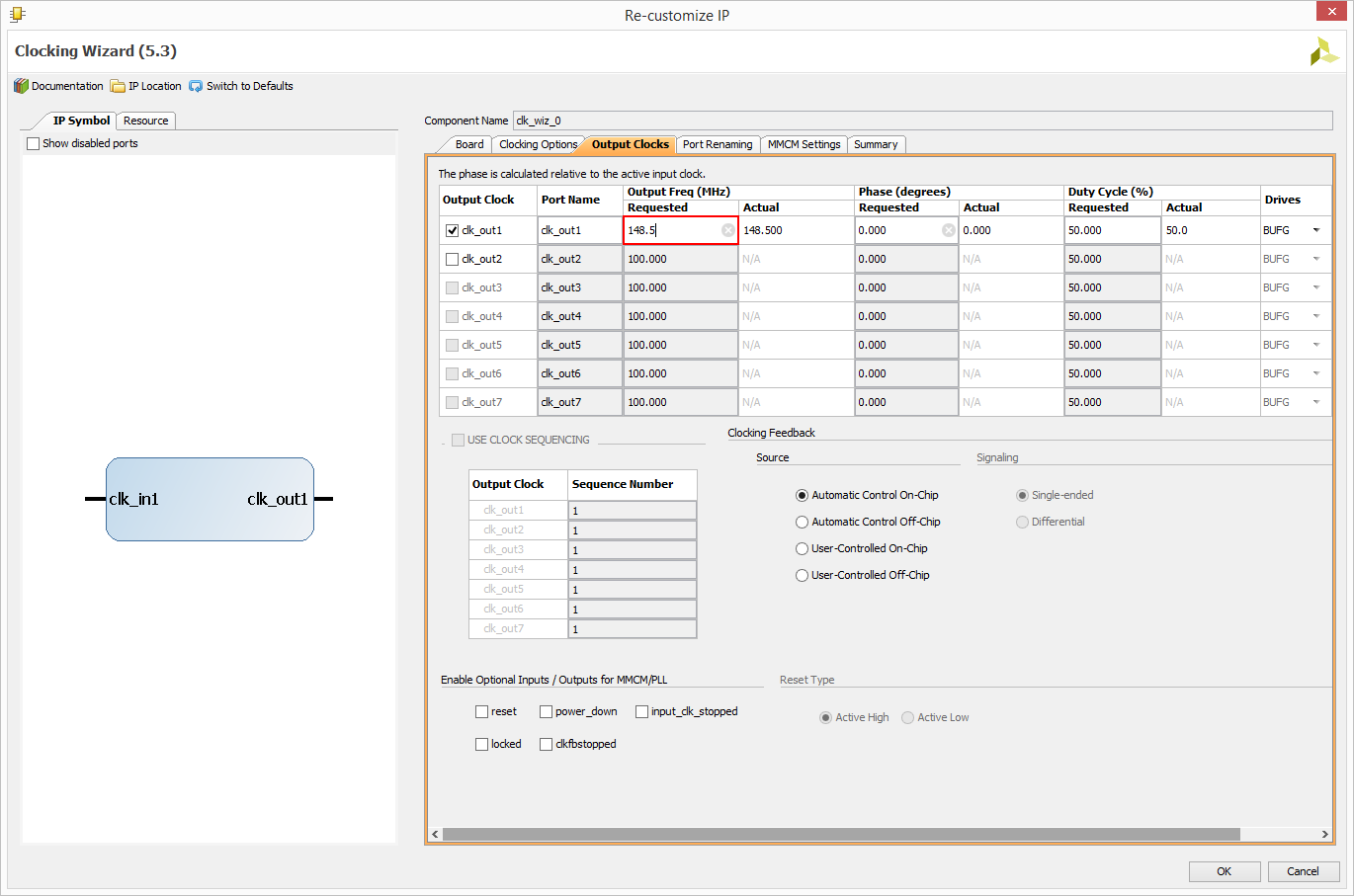
Next select Project Manager in the Flow Navigator. In the Hierarchy tab of the Sources box, expand top.vhd under Design Sources and double click on clk_div_inst. Change the clk_out1 Requested frequency - circled in red below - to the required pxl_clk frequency specified in the selected resolution's Sync Generation comment block. Select Ok, then Generate in the Generate Output Products dialog that pops up. Once the bitstream has been generated, reprogram your board with the new hardware.


