This is an old revision of the document!
Zybo XADC Demo
Overview
A project that instantiates the XADC IP Core and measures an analog voltage
Features Used
| Not Used | Used | |
|---|---|---|
| 4 user switches | X | |
| 4 user LEDs | X | |
| 5 user push buttons | X | |
| USB-UART Bridge | X | |
| Micro SD card connector | X | |
| HDMI Sink and HDMI Source | X | |
| 16 Bit VGA port | X | |
| Audio codec w/ three 3.5mm jacks | X | |
| User EEPROM | X | |
| 10/100/1000 Ethernet PHY | X | |
| 512MiB 800Mt/s DDR3 Memory | X | |
| Serial Flash | X | |
| Five Pmod ports | X | |
| Pmod for XADC signals | X | |
| USB HID Host | X |
Description
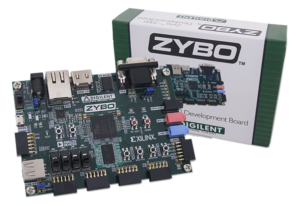
This simple XADC demo is a verilog project made to demonstrate the ADC functionality of the Zybo
- The LED associated with a specific channel brightens when the read voltage goes up.
- The four user switches enable each XADC channel to be read from.
This demo uses the XADC Pmod header, which has differential ports 1, 2, 3, and 4 connected to the XADC pins 14, 7, 15, and 6, respectively. This can be seen in the schematic below.

Prerequisites
Skills
- Basic familiarity with Vivado
- This experience can be found by walking through our “Getting Started with Vivado” guide
Hardware
- Zybo board
- Micro-USB cable
- Breadboard
- Resistors
- Wire
Software
- Vivado Design Suite 2015.X
- Newer/older versions can be used, but the procedure may vary slightly
Downloads
Zybo Support Repository – GIT Repo
How to...
1. Generate the Project
1.1) Download the repository linked in the download section and place it in the location of your choosing.
1.2) Generate the XADC project in the Projects folder by following this guide before continuing: How to Generate a Project from Digilent's Github
2. Build the Project
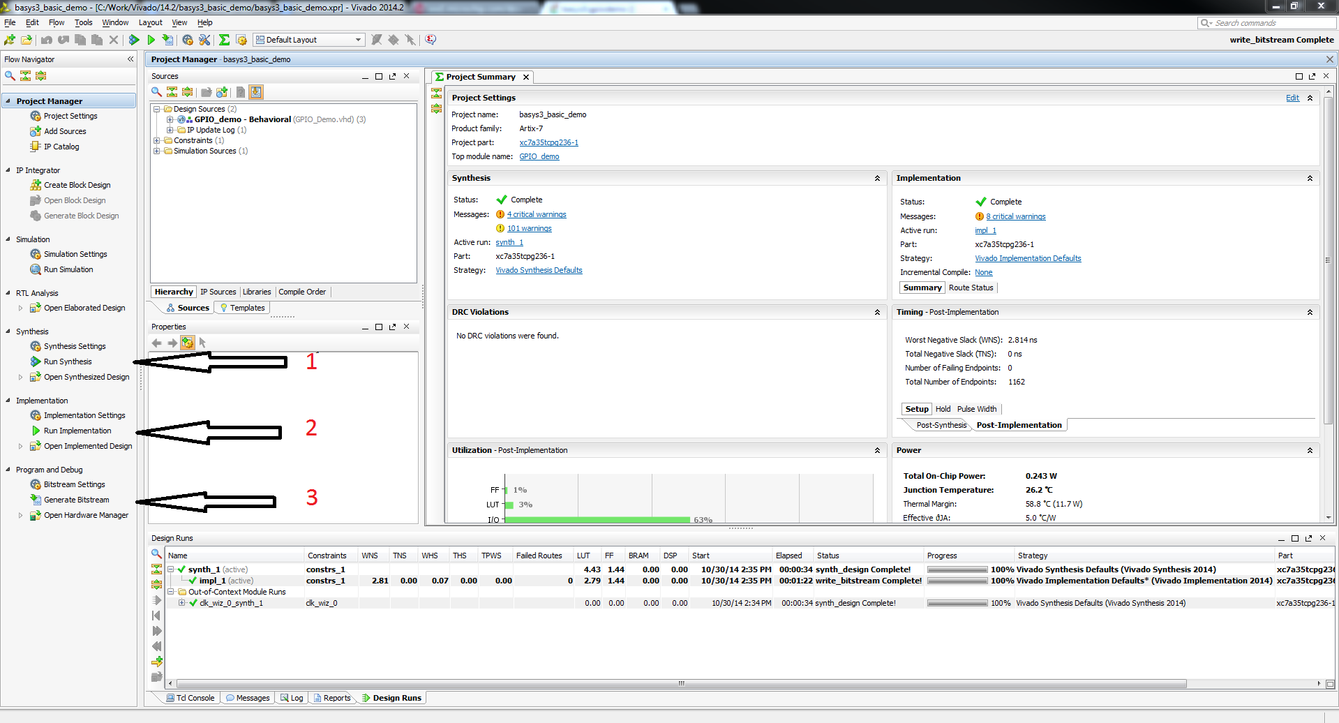
2.1) Click Generate Bitstream on the left hand menu towards the bottom. Vivado will run through both Run Synthesis and Run Implementation before it generates the bitstream automatically.
Note: If you want, you can click each step by itself in the order of Run Synthesis, Run Implementation and then Generate Bitstream.
3. Program the Board
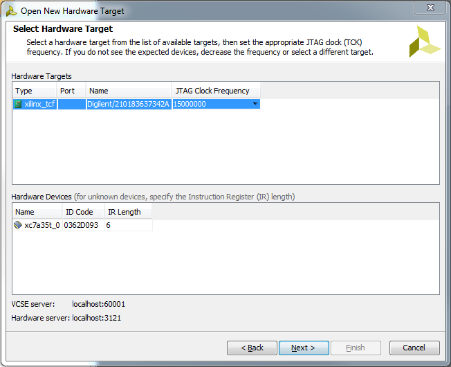
3.2) Click program to load the project onto your Zybo.
4. Run the Project
This portion will help you run the demo and observe all its features. The demo reads analog data in from each enabled xadc channel (set the associated switch to the high position to enable that channel) and sets the brightness on the associated led linearly. Higher voltage = brighter led.
4.1 Setting up the circuit
The pictures below used a resistor ladder to show the different brightness values the demo puts out. This demo can be used to measure any voltage between 0 and 1 volt. The brighter the led, the closer to 1 the voltage is. The voltages below are 1.0V, 0.5V, 0.2V, and 0.1V. The circuit below uses a chain of ten 1KOhm resistors in series with two parallel 47KOhm resistors tied to the 3V3 and GND pins of the XADC Pmod header to create these voltages.


