This is an old revision of the document!
Arty Pmod VGA Demo
Overview
Features Used
| Not Used | Used | |
|---|---|---|
| 4 User Switches | X | |
| 4 User LEDs | X | |
| 4 User RGB LEDSs | X | |
| 4 User Push Buttons | X | |
| 4 Pmod Connectors | X | |
| XADC Analog Input | X | |
| USB-UART Bridge | X | |
| Serial Flash for Application Data | X |
Description
This simple VGA Demo project demonstrates usage of a Pmod VGA connected to the Arty's Pmod ports. The behavior is as follows:
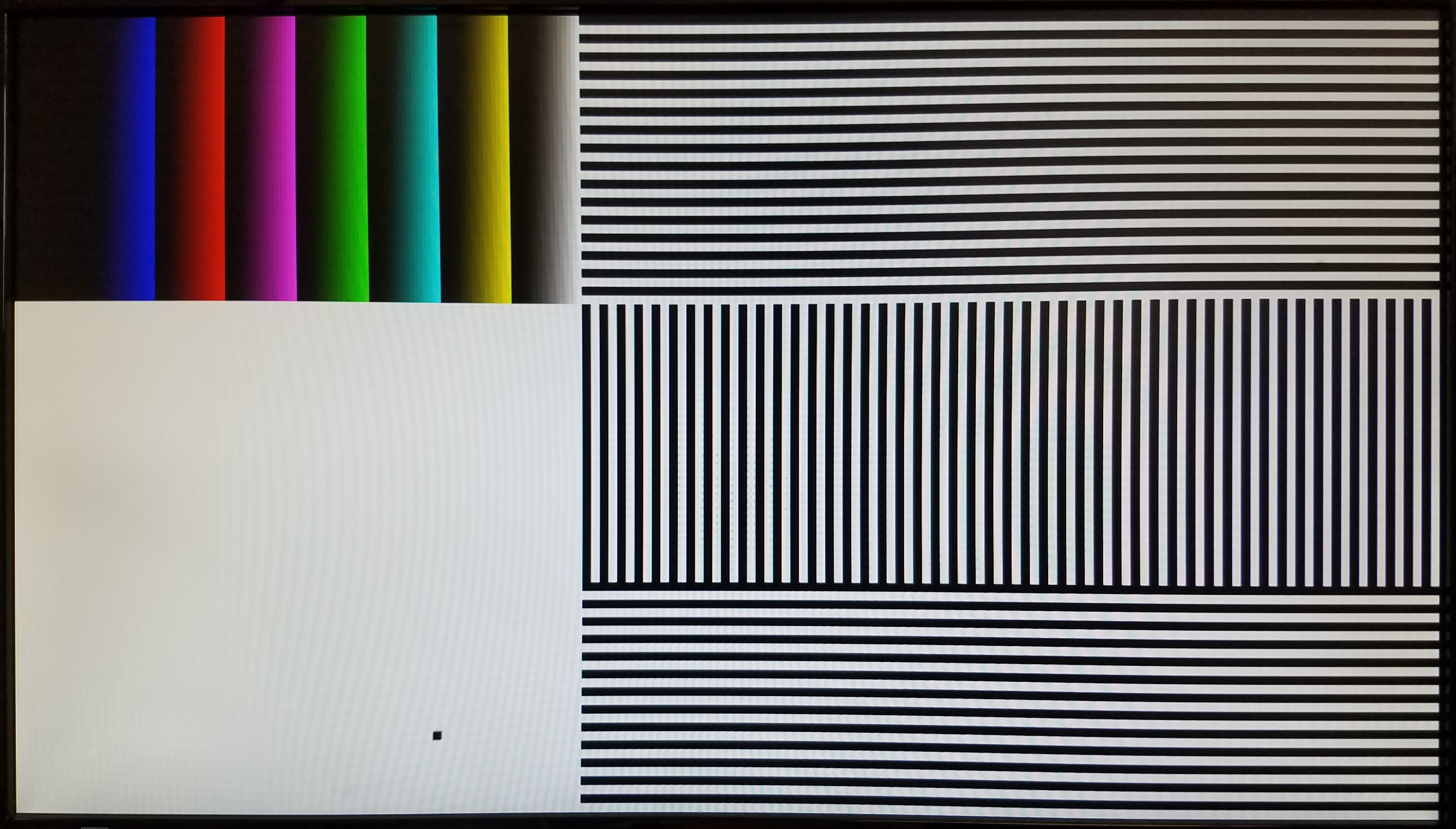
- A bouncing box and black, white, and multiple colors of bars are displayed on a connected VGA monitor.
- The Pmod VGA is controlled by the Arty through Pmod ports JB and JC.
- The screen resolution is configurable through HDL code.
Prerequisites
Hardware
- Arty FPGA board
- Pmod VGA
- Micro-USB cable
- VGA monitor and cable
Software
- Vivado Design Suite 2016.4
- Newer versions can be used, but the procedure may vary slightly
- Digilent Board Support Files for Vivado
- Follow the Vivado Board Files for Digilent 7-Series FPGA Boards guide on how to install Board Support Files for Vivado.
Downloads
Arty Pmod VGA Project Repository – GIT Repo
How to...
1. Generate the Project
1.1) Download the zip archive linked in the downloads section and place it in the location of your choosing.
1.2) Extract the project source from the downloaded archive.
1.3) Generate the PmodVGA project by following this guide before continuing: How to Generate a Project from Digilent's Github
2. Build the Project
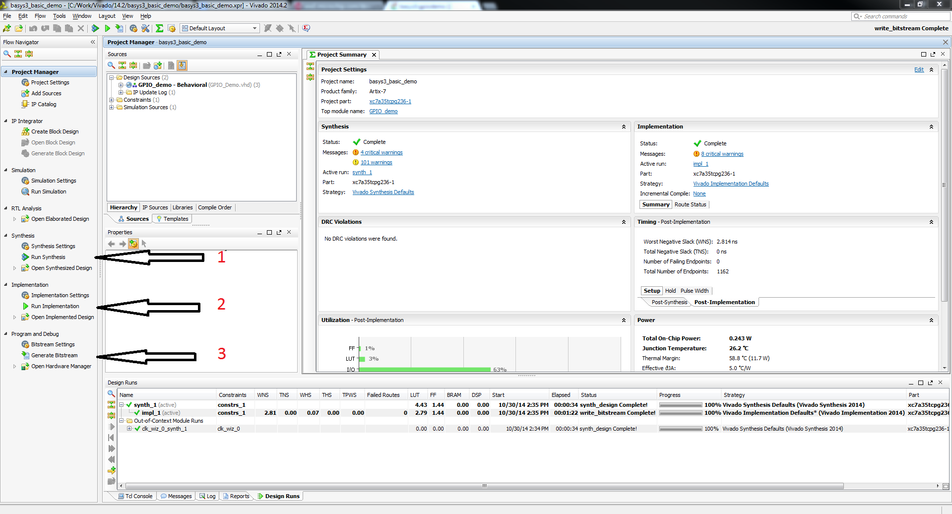
2.1) Click Generate Bitstream on the left hand menu towards the bottom. Vivado will run through both Run Synthesis and Run Implementation before it generates the bitstream automatically.
Note: If you want, you can click each step by itself in the order of Run Synthesis, Run Implementation and then Generate Bitstream.
3. Program the Board
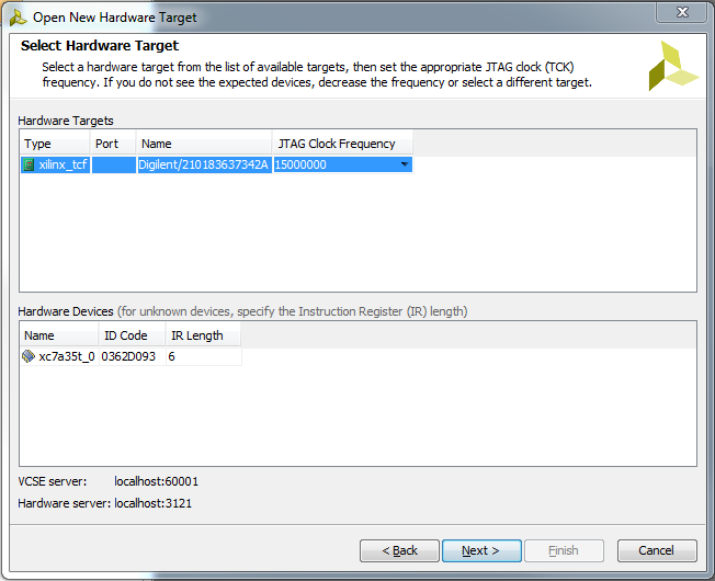
3.2) Click Program device to load the project onto your Arty.
4. Run the Project
This portion will help you run the demo and observe all its features.
4.1) Set up hardware
Connect the Pmod VGA to Pmod ports JB and JC. Connect the Pmod VGA's VGA port to the VGA port on your monitor.
4.3) Changing the resolution
You may want to change the display resolution if your VGA monitor does not support 1080p, or you want to modify the demo for a specific application.
To select a different display resolution, select the appropriate set of Sync Generation constants for your target resolution from the list starting at line 47 of top.vhd. Uncomment the ten corresponding constants, FRAME_WIDTH through V_POL, and comment out the default versions of those same constants. The default resolution is 1920×1080 @ 60Hz.
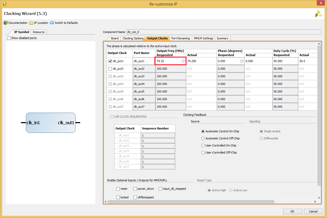
Next select Project Manager in the Flow Navigator. In the Hierarchy tab of the Sources box, expand top under Design Sources and double click on clk_div_inst. Change the clk_out1 Requested frequency - circled in red below - to the required pxl_clk frequency specified in the selected resolution's Sync Generation comment block. Select Ok, then Generate in the Generate Output Products dialog that pops up. To reprogram your board with the new hardware, return to Step 2.


