This is an old revision of the document!
Analog Discovery 2 - Using the Waveform Generator
Waveform generators are used to test circuits by generating defined signals that are then fed into the circuit under analysis. You can have an arbitrary waveform generator (AWG) that outputs whatever waveform the user has defined, or you can have a function generator that outputs predefined signals like sine, square, etc. The waveform generator on the Analog Discovery 2 along with WaveForms 2015 software is a combination of both generators. The Analog Discovery 2 is also small, compact, and extremely affordable compared to many generators that can cost hundreds or even thousands of dollars.
Inventory
-
- You may also use the Analog Discovery legacy or the Electronics Explorer Board with WaveForms 2015. There are some slight differences in functionality between the Analog Discovery Legacy, Analog Discovery 2, and the Electronics Explorer Board, but nothing that will prevent you from following along if you have one of the other tools.
- A computer with USB port to run the software
Step 1: The Waveform Generator
There isn't much to cover as far as background material for a waveform generator, so let's get started. If you want some help getting your device calibrated, or installing WaveForms 2015, check out this quick start Instructable collection.
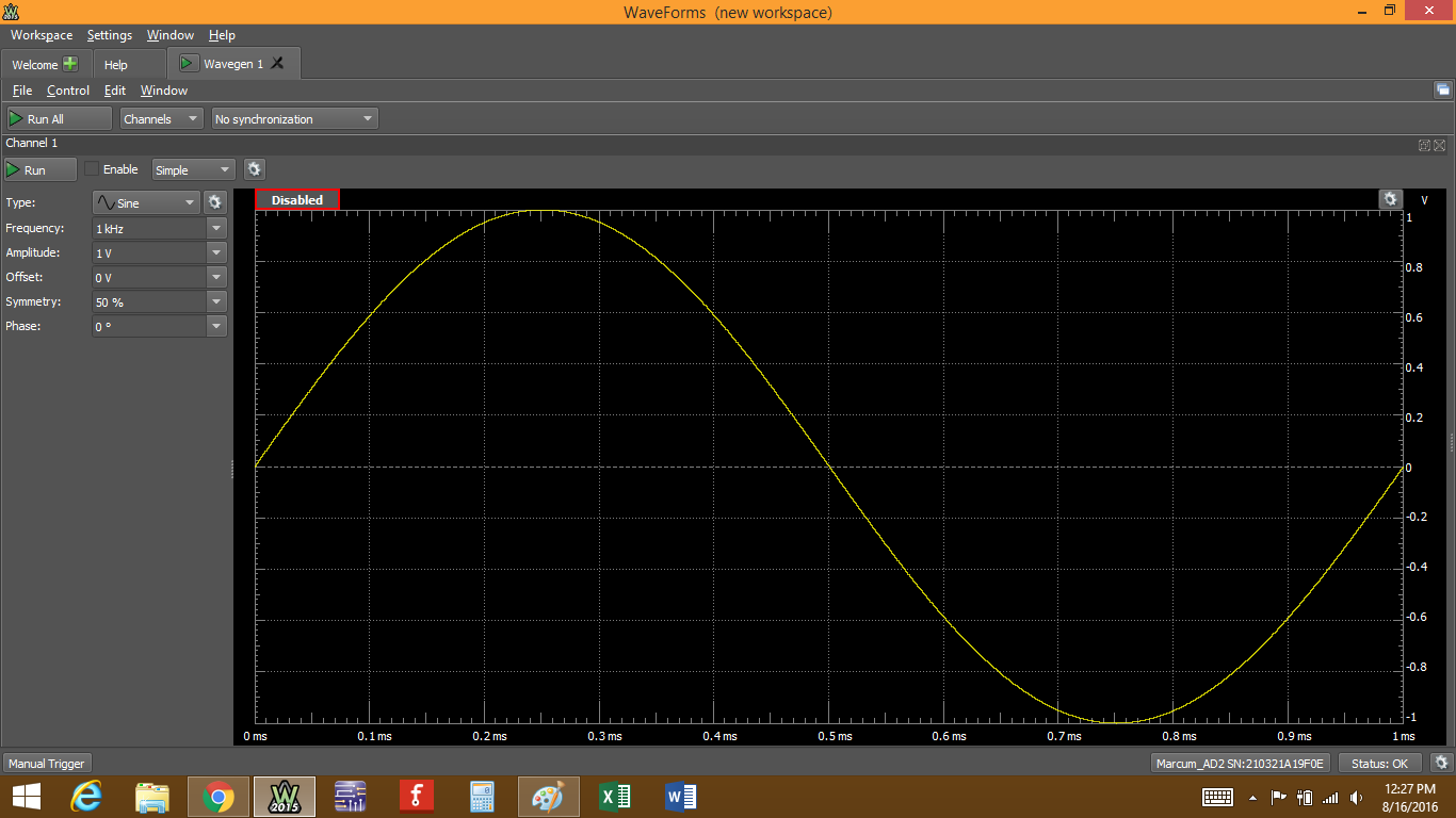
Once you have your Analog Discovery 2 and WaveForms all set up, open the waveform generator by clicking on the “Wavegen” button.
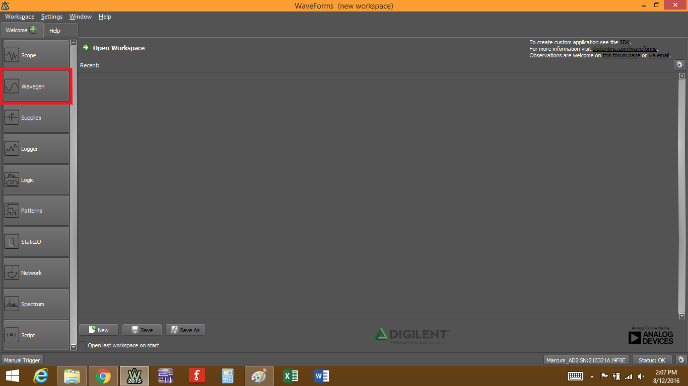
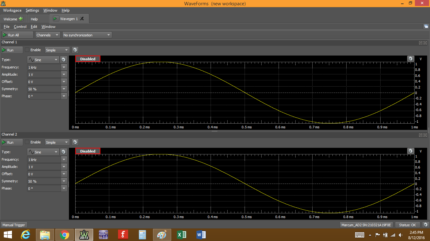
The waveform generator tool will open.
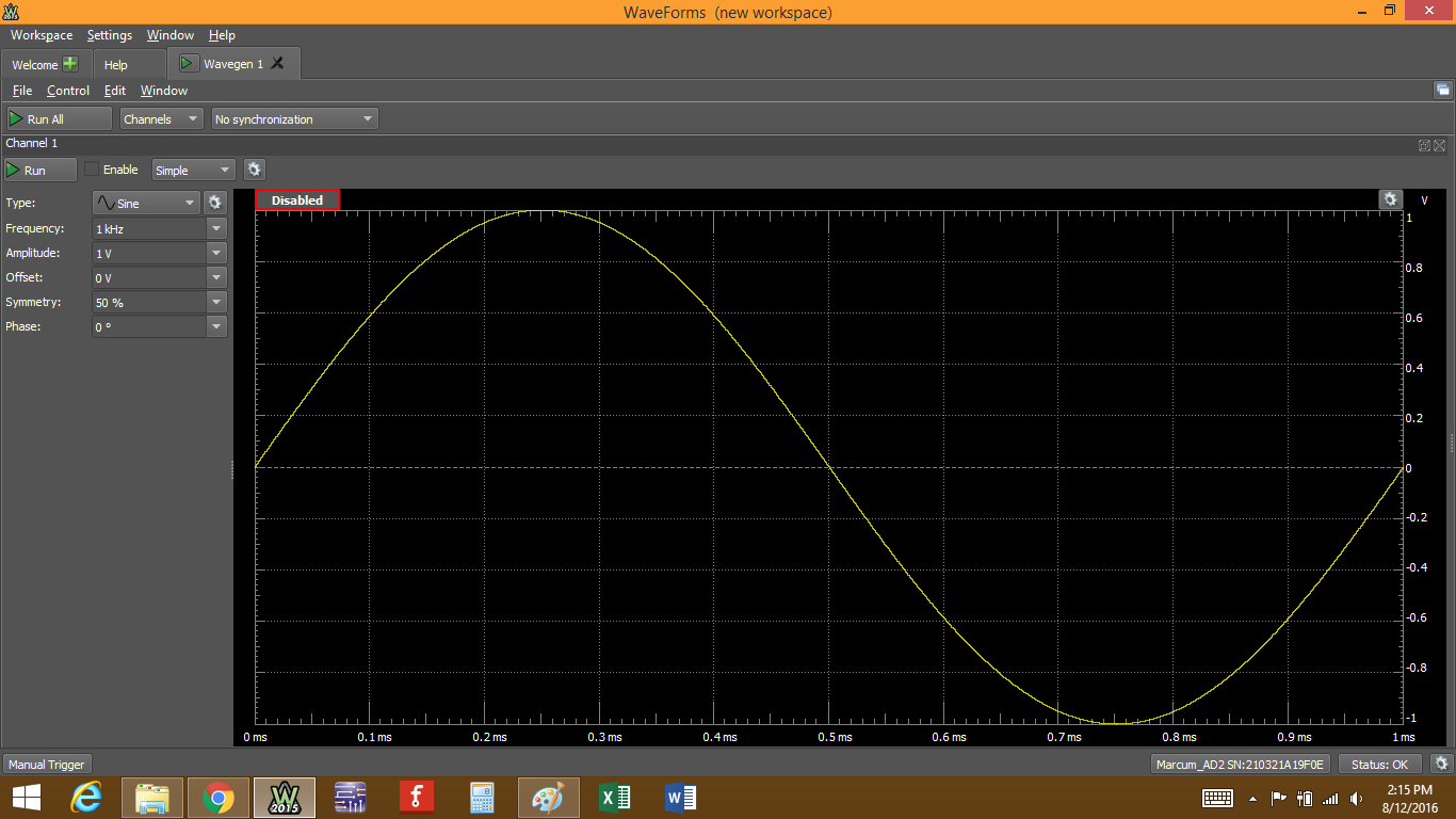
There are three main areas to pay attention to:
- The control toolbar
- The configuration panels, which will change based on the type of waveform you want to generate.
- The preview plot
Let's take them one at a time, starting with the control toolbar.
Step 2: The Control Toolbar
There are only a few controls associated with the control toolbar.

- “File” lets you open a New Wavegen instance, Open or Save a project, or Export the current wavegen data, either as an image or as a raw data file formatted in *.csv, *.txt, or *.tdms, which is specific to National Instruments.
- “Control” provides acces to the Run All and Stop All actions, which will turn on or off all enabled wavegen channels.
- “Edit” lets you copy and swap channels from one to the other.
- “Window lets you switch between different waveforms windows that are open, or access the Waveforms Help window.
- Below that, you will find the “Run All” button. This will control the function generation on all channels that have been turned on, even overriding the “Enable” box (more on that in the next step). Channels can be opened/closed from the “Channels” drop-down button next to it. All channels that have a check mark have been opened and can be viewed in their own separate pane.
Clicking on the “No synchronization” button gives you some synchronization options between the different channels and allows you to edit different trigger options. This is useful when you need to run multiple signals through the same circuit, or have one or both channels trigger at a specific time. For most applications, the default is usually appropriate.

In “no synchronization mode, no synchronization or trigger parameters are available.
In “Independent” mode, the channels are working independently. The trigger-wait-run-repeat settings can be independently configured for each channel and opened in each channel's specific pane. If you modify the trigger settings of a channel, its signal generation starts over from the beginning and synchronization with the other channels is lost.
In “Synchronization” mode, the trigger-wait-run-repeat settings are the same for all selected channels within the same instrument instance. Modifying the settings of one of the channels causes both to be restarted. A run time value other than continuous should be used to periodically re-synchronize the channels. This has to be done because the actual frequencies might be approximates of the desired values and small errors accumulate until, after several cycles, the channel's phase will slide.
The “Auto” synchronization mode is similar to the “Synchronized” mode where run time is automatically adjusted to the longest period from all channel's settings (depending on signal frequency sweep/damp time, or AM/FM modulator frequency).
For the trigger settings, the button displayed below in Fig. 9 lets you determine what type of trigger source you want. You can select “none”, or use some external signal, or even one of the Waveforms tools, like the Oscilloscope. You can also trigger the signal manually by setting the trigger to “manual” and then clicking on “Manual Trigger” in the bottom left corner of the window.

The button in Fig. 11 below lets you set a wait time. Once the trigger condition has been met, the signal will enter the idle condition, outputting the offset value for that amount of time. Once that time has expired, the output will then be the selected waveform type. Any time from 20ns to 24 hours is valid, or you can select “none” to not wait at all.

The button displayed in Fig. 12 lets you set how long the signal will run once the Wavegen has been triggered and any wait time has expired. Any time from 20 ns to 24 hr can be selected, or you can choose “continuous” to not have the signal ever reset. Be aware that choosing “continuous” can introduce an accumulated rounding error to the signal output over time, resulting in a phase shift. Setting your run time to some integer multiple of your frequency time base (e.g. for a 1 kHz signal, enter a 1 ms run time) will regularly reset the signal output and any accumulated error will continuously be reset to 0.
The button in Fig. 13 lets you set how many times you want the set signal to repeat before returning the output to idel state. You can set this to any value between 1 and 30,000 cycles, or choose infinite.

If you check “Repeat Trigger”, you will have to trigger the wavegen to output for the number of cycles you entered in the “Repeat” box. For example, if you have “manual” selected, under “5” in the repeat box, and check “repeat trigger”, you will have to click the manual trigger button at the bottom five times. The wavegen output will idle and arm between triggers, and then idle and reset to ready state after 5 triggers. By unchecking the box, the wavegen will automatically output the chosen waveform for the set number of cycles without the need of additional trigger instances.
The following example involves some details from the next step, but demonstrates the trigger functionality well. The settings will produce a 1kHz signal at 1V offset and 1V amplitude. The trigger is set to manual, and once triggered, the output will wait for 500μs, then output for 2ms. This cycle will automatically repeat 2 times, then the output will enter idle state, outputting 1V DC. The whole thing will take 5ms to happen.
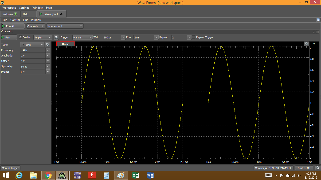
By connecting the Waveforms Oscilloscope, we can verify our settings.
The scope window settings have been adjusted to make the signal more obvious. The signal is idle until triggered, at which point it enters the first wait time at -0.6ms, waits for 500μs, then completes that first cycle at 1.9ms. The second cycle begins its wait period at the same time, waits for 500μs, and then completes at 4.4ms. The output is then in idle, which is the offset value of 1V.
Step 3: The Configuration Panes
There are several different configuration panes depending on which type of signal you want to generate.
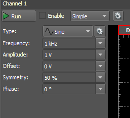
There are some functions that are the same regardless of what signal you are generating.
Clicking “Run” will turn on/off only that channel.

The “Enable” box can be overridden several different ways, but if disabled it will turn off all outputs from that specific channel, including idle signals. Read on for more clarification about idle state signals.
We'll skip the “Simple” button for just a minute.

Clicking the top gear icon allows you to determine what the wavegen channel will output while in an idle state. You can choose either the initial value or the offset. For many signals this will be the same value, but if you change the phase for example, these values will be different. Be aware that stopping the waveform output does not disable the idle output, so if you turn it off but have changed the offset of initial values to something not 0V, there will still be a DC signal on the wavegen channel even when you have turned it off. The only way to fully disable this idle output and prevent shorting is either keep the offset or initial values at 0V or uncheck the “Enable box.

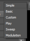
The “Simple” drop-down menu has a lot of options, and each of those options has a lot of different settings.

This menu is where there are some major differences, so let's look at those one at a time.
Step 4: The Configuration Pane: Simple
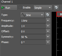
The first option is “Simple” and should be the default when you open the wavegen tool.
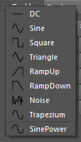
From here you can set the type of signal you want from the “Type” drop-down menu. Figure 24 displays the several options available.

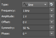
Once you choose a waveform type, you have several editable parameters below that. Any edits you make will update on the plot to the right.
Most signal types have all parameters available. For a “DC” signal, there is no frequency, amplitude, symmetry, or phase, so you can only change the offset to any value between +/-5V. This can be used to provide additional power supplies, separate from the dedicated power supply pins. For “Noise”, “Symmetry” and “Phase” are disabled. For SinePower, “Symmetry” becomes “Power”. More on that below.
“Frequency” lets you determine the frequency of your output signal. The units are in Hz, and you can enter any value from 100μHz to 10MHz. You can enter up to 6 decimal places, though some rounding will occur. If you enter a value such as “3001.234567 Hz”, WaveForms will trim it to 3.001235 kHz. For a “Noise” signal, frequency determines the DAC update rate.
“Amplitude” tells you how far your signal will travel above and below your offset value. So a 1V amplitude will travel to +1V, and then to -1V, giving a peak-to-peak value of 2V, 1VC in each direction. You can enter any value between +/-5V, but be aware of your offset value in order to prevent clipping.
“Offset” allows you to change where your center value is in relation to 0 V. It imparts a DC bias onto whatever AC signal you are generating. A 1 V offset will move the entire signal up 1 V. -1 V will move it down 1 V. You can enter any value between +/- 5 V, but in order to prevent clipping your signal, you need to make sure that your offset value added with your amplitude value doesn't exceed either +5 V or -5 V. For example, if you give your signal on offset of either +3 V or -3 V, any amplitude value that is greater than 2 V will result in clipping the top or bottom of your signal, respectively.
“Symmetry” is an interesting parameter and changes different signals in different ways. I encourage you to play around with this setting with each of the different signals to really get a good idea of what it does. This parameter is turned off for a “Noise” signal.
The “Symmetry” parameter becomes a “Power” parameter for a SinePower waveform. If the power value is greater than 0, the sine function outputs sin(x))(100 /(100 - power)). If the power value is less than 0, the function becomes sin(x)((100 + power) / 100).
“Phase” lets you shift your signal horizontally along the time base, but in units of °. You can enter any value from 0-360°.
Step: The Configuration Pane: Basic
“Basic” gives you all the same waveform and parameter options as “Simple”, but with much more control over each parameter.
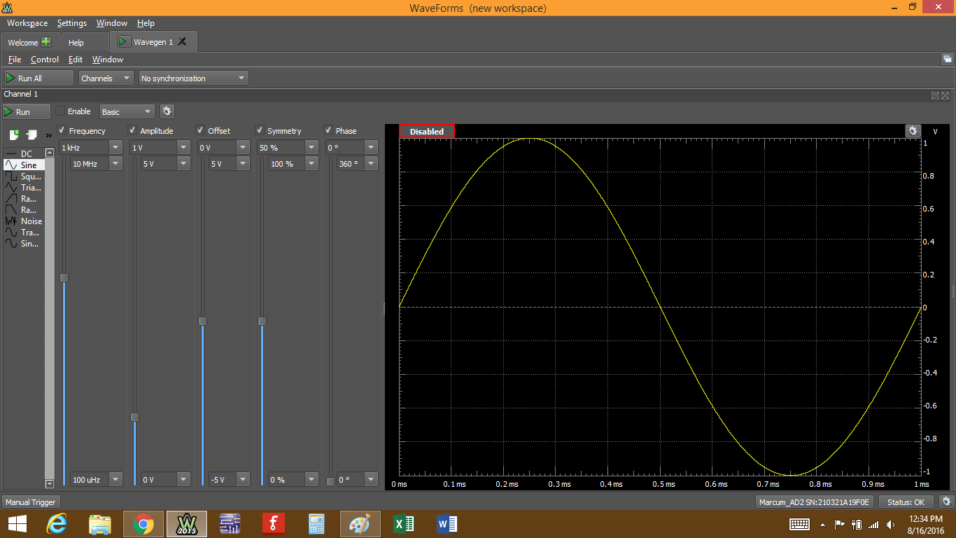
On the left you have all of your signal type options. To the right of that, you now have sliders for each parameter.
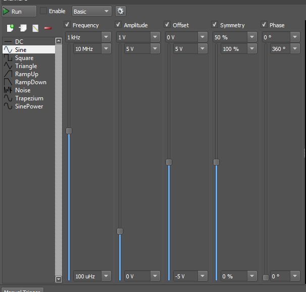
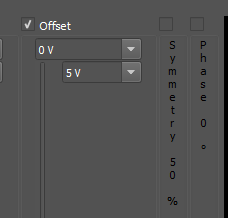
You can hard set the range of each slider, with the slider itself determining the actual value. For example, if you are trying to find the exact cutoff frequency of a specific filter, you can set your top bottom frequency values to just above and below your calculated value. Then use the slider to adjust the frequency within that window to pinpoint the cutoff exactly. Sliders can be adjusted in real time while the Wavegen is running and while the output is connected to any other Waveforms tool or a circuit.
Above each slider you can click on the Frequency button to open or close the slider. It doesn't enable/disable the parameter, but minimizes the slider and displays the parameter name and value vertically.

Step 6: The Configuration Pane: Custom
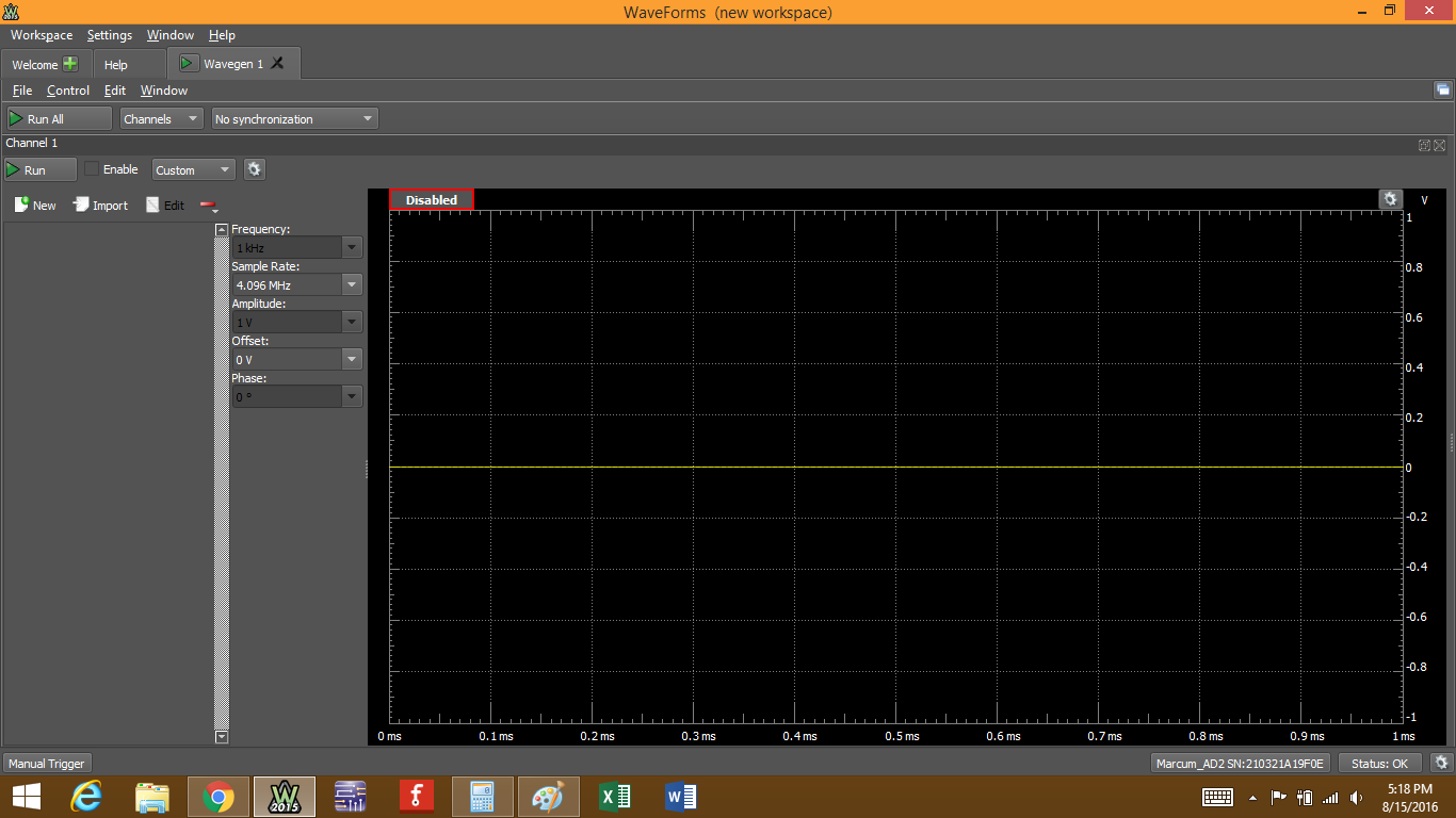
“Custom” can be accessed a few different ways. The first is by selecting “Custom” from the drop down menu, at which point you will see the window as displayed in Fig. 31.
Click on “New” to open the custom window.
“New” is also available from the “Basic” signal generator option.

From “Simple”, “Sweep”, or “Modulation”, you can click on the gear next to the type drop-down menu. From there, click on “New” to open the “Custom” waveform editor window.
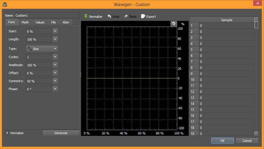
However you choose to open the custom waveform editor window, you have the same options from there across the top of the window.
- “Name” lets you assign a name to the waveform
- “Normalize” will normalize the plot values between -100% and +100% for the y-axis, and 0% and +100% for the x-axis.
- “Undo/Redo” lets you undo or redo any changes made.
- “Export” allows you to export the current custom waveform to a file. You can export as an image, or as raw data in *.csv, *.txt, or *.tdms formats.
In the middle you see the plot of the current custom waveform. You can add/remove labels and change the width of the plot trace by clicking on the gear icon. The plot axes are listed in terms of percentage. When you edit and save your waveform, whatever you have on the plot becomes one complete cycle for the new waveform. You can later change the frequency of the waveform, but more on that later.

On the right side you have the “Sample box”. There are 4096 samples that each correspond to a data point on the plot. You can edit each data point individually to really customize your own waveform, which would be very time-consuming, but is always an option. Whatever waveform you decide on; the Sample box will update the values as edits are made.
On the left side you have multiple tabs available that you can use to define your waveform (the tabs are described in the sections below). This is where the magic happens! Note that until you click “OK”, you can edit the current waveform from any tab at any point in the process. You're not restricted to using only one tab to generate your own waveform. If you don't like the results, simply click “Undo” and try again.

Function
The “Function” tab includes several editable parameters that may be a bit confusing. Most of these values are in units of percentage, which will relate to the actual output once you save it.

- “Start” and “Length” refer to the x-axis on the plot. “Start” is where the signal will start, and ” Length” determines for how long.
- “Type” gives the same waveform list we've seen previously.
- “Cycles” determines how many times the selected waveform will repeat within thew plot percentages you defined with “Start” and “Lentgh”. This number must be an integer, but with some creativity you can get partial signals.
- “Amplitude” sets the percentage of the available window the signal will use for amplitude.
- “Offset” moves the signal vertically in relation to center.
- “Symmetry” and “Phase” have the same effect as before.
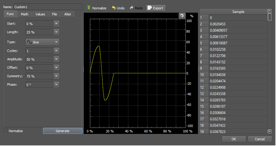
Now, for an example, make the following edits:
- 25% in “Length”
- 50% for “Amplitude”
- 75% for “Symmetry”
- Uncheck “Normalize”
- Click on “Generate” and what you have defined so far will appear on the plot.
If you leave “Normalize” checked, the plot will normalize to 100% amplitude because there is nothing to compare to in order to determine where 50% should be.
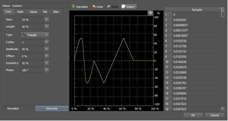
Now the interesting part! We don't want to overwrite the sine wave, but let's add a triangle wave. Make the following edits:
- 25% for “Start”
- 50% for “Length”
- Select “Triangle” type
- 50% “Symmetry”
- 180° “Phase”
- Click on “Generate” and the plot will update.
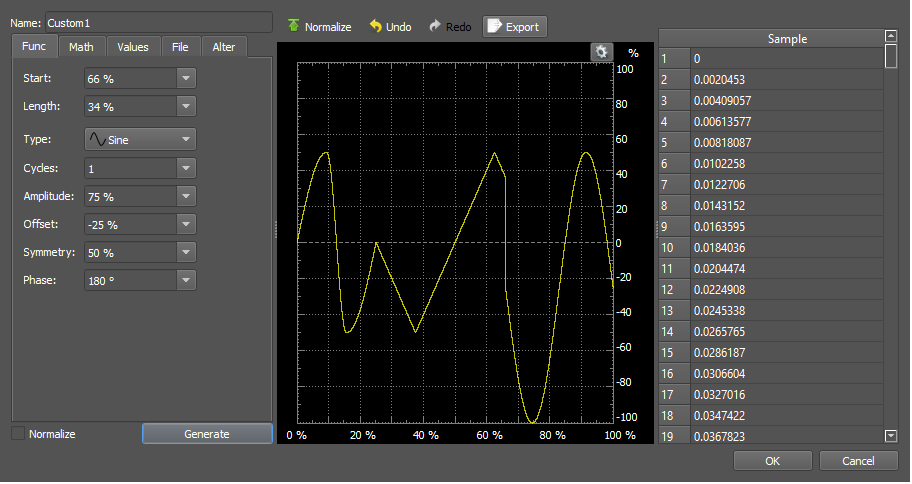
Let's add one more piece to the plot before saving it. Edit as follows:
- 66% “Start”
- 34% “Lenght”
- Select “Sine” type
- 75% “Amplitude”
- -25% “Offset”
- Click on “Generate” and the plot will update.
Once you have your waveform defined, click on “OK” to save. It will appear in the main plot window.

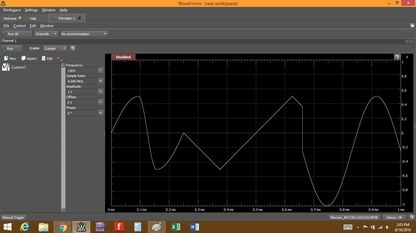
Be aware that once you save your custom signal, it will also appear in the “Type” menus for all of the other wavegen signal options. For example, if you generate and save a custom signal while in “Basic”, you can then select the same signal from the type menu for “Simple”, “Modulation”, ect. The only place it won't show up is if you try to generate a new custom waveform and try to select it from the “type” drop-down menu within the custom editor window.
On the far left you will see all of your custom signals. You can add as many as you want. Next to that you can edit the wavegen output parameters like frequency or amplitude.
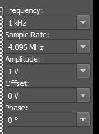
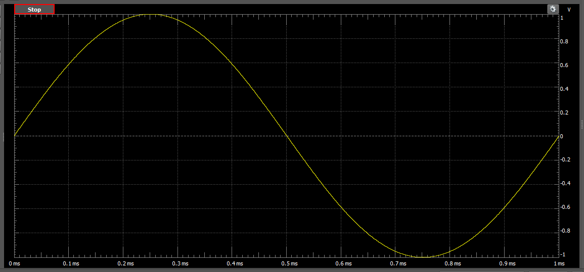
The frequency defaults to 1kHz, so whatever waveform you design will complete one full cycle in 1ms by default. Below that you have the sample rate, which defaults to 4.096MHz. Remember the “Sample” box won the right side of the editor window? There were 4096 samples that defined one complete cycle of the waveform we designed. To achieve 1kHz, we need to sample all 4096 samples 1000 times per second, hence 4.096MHz. If we adjust the frequency, the sample rate will adjust to match. Alternatively, changing the sample rate will adjust the frequency to match. “Amplitude” will adjust the max amplitude of the entire custom signal. “Offset” will move the entire custom signal velocity on the plot. “Phase” will shift the entire custom signal horizontally.
Math
Now let's take a look at the “Math” tab.
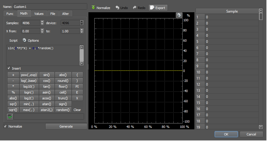
You can simply type in whatever math function you want using JavaScript syntax.
The “Samples” box lets you determine how many data points will actually register in the plot. WaveForms will divide the plot evenly between each point and then calculate the value at each pint according to the function determined by the script. ONce saved, the wavegen output will hold each data point value for an amount of time equal to 1/(# of samples) of the signal period. More on this later.
“X from” and “to” define the range of X values used in the defined script.
Checking “Insert” will open a small window with a number of predefined JavaScript math functions.

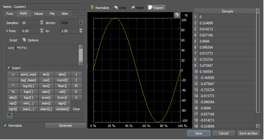
Let's make some edits to define our own signal.
- Change “Samples” to 20
- Edit the default function script to be “sin(2*PI*X)
- Uncheck “Normalize”
- Click on “Generate” and the editor window will look like Fig. 58 below.
It looks alright, but click on “Save” to see what the actual plot output will be.
Values
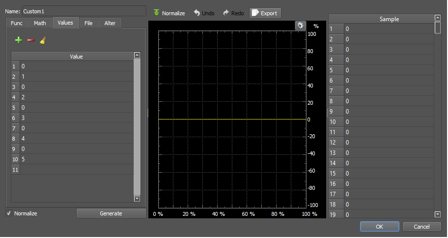
Next is the “Values” tab. When you open the tab, there is a table of default values on the left.
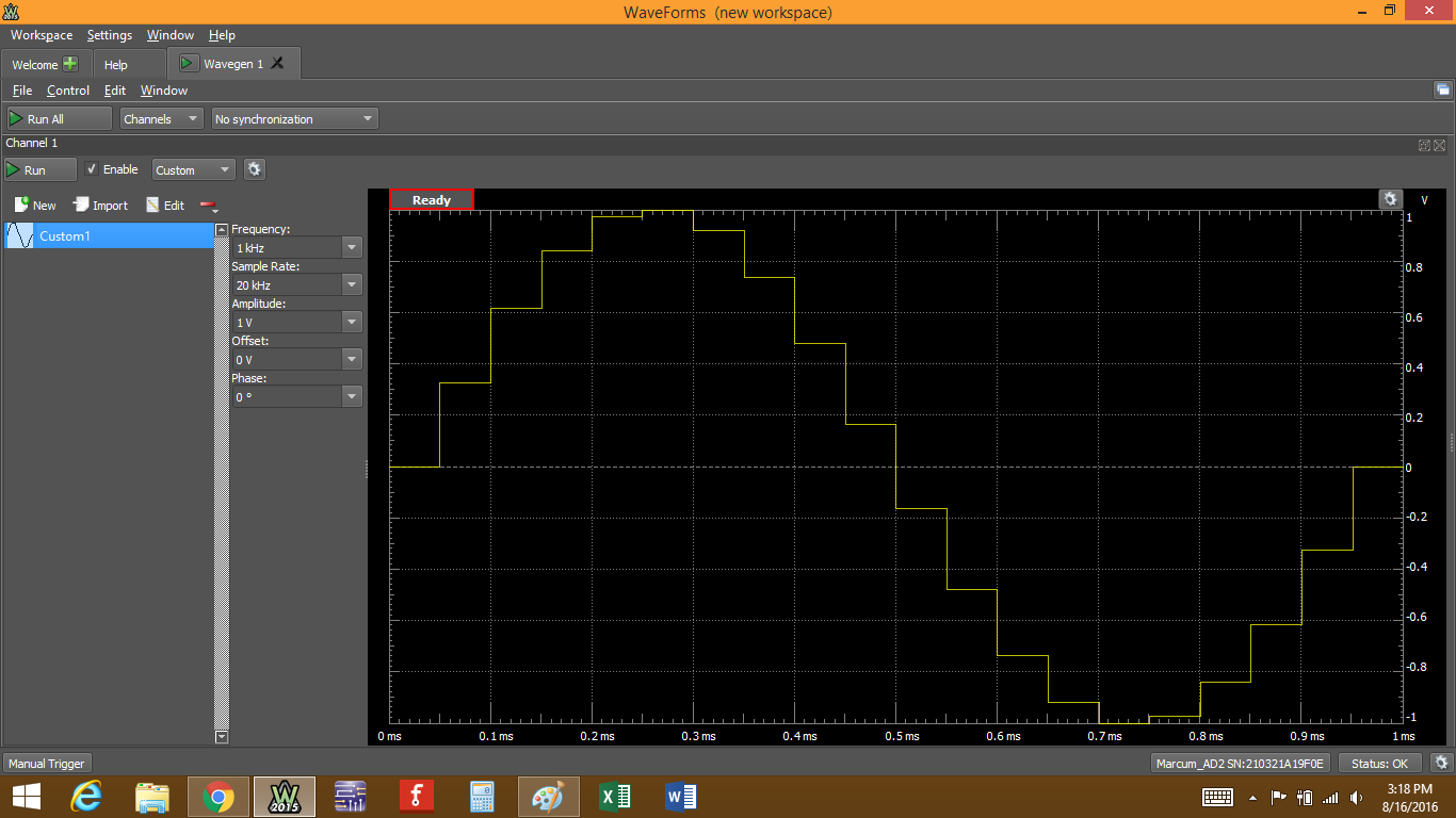
This option is really good for building step functions. You can have up to 100 values in the table on the left. The “Sample” table on the right is the list of all 4096 samples that the device can have in its buffer. These will auto-populate once you generate you signal. Remember that whatever you see in the editor plot window is what will become one full period of your signal. You can use any value you want, and with “Normalize” checked, the values will scale relative to the max and min values given to fit in the plot. We can see that with the default values.
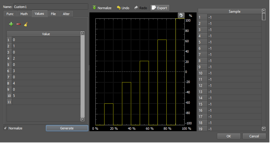
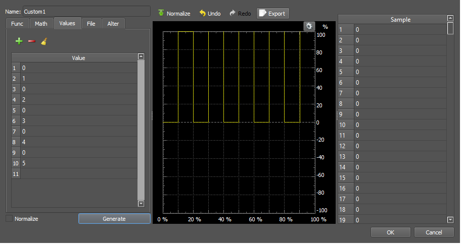
With “Normalize” unchecked, any value greater than 1 or less than -1 will go off the top/bottom edge of the plot and will be cut off and ignored. Figure 62 is a plot of the same values, but with “Normalize” unchecked.
The final wavegen output will simply be a square wave, not a step like before.
File
The next option is “File”
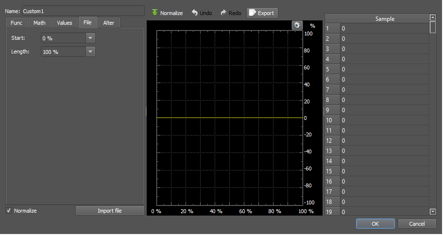
You can import a saved waveform file, and by adjusting the “Start” and “Length”, you can determine how much of the file is imported, starting with the file's left-most plot value and working left to right.
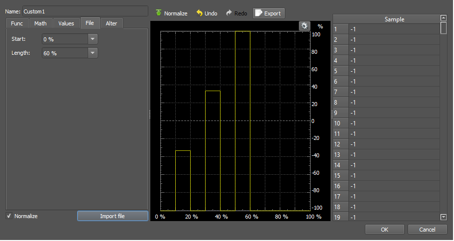
A copy of the default waveforms from the “Values” table with “Normalize” checked has been saved. By setting “Length” to 60%, you will get the following:
The first three steps import, and then are normalized to the size of the plot window. Once “OK” is clicked, you can then adjust amplitude and offset from the main window to move the wavegen output to where you would like it.
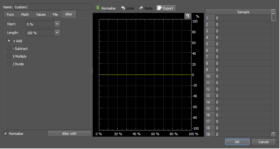
From here you can take any function you've already designed and alter it with another function. When you click “Alter with”, a second custom window will open. You can generate another signal, including using the “Alter” tab again. Once you click “OK”, you'll import the new signal into the previous “Alter” instance, and from there you can alter the current signal again.
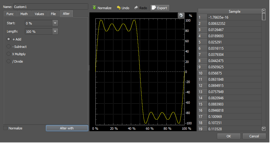
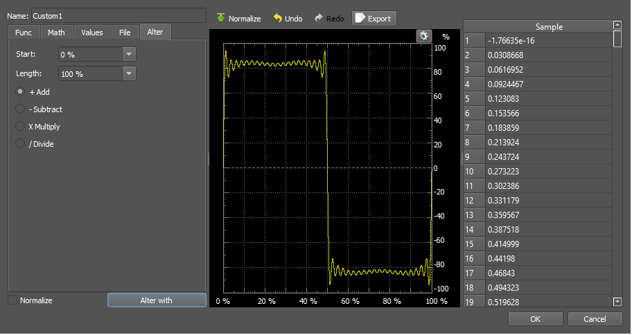
Let's use the “Alter” tab to see how a square wave is made up of summed sine waves.
- Start in the “Math” tab
- Make sure “Normalize” is checked
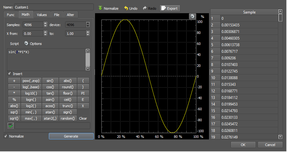
- Generate a sine waveform by using the function “sin(2*PI*X)”
- DON'T click on “OK” yet
- Then from the “Alter” tab, make sure ”+ Add” is selected, then click “Alter with”
In the new window that opens, click the “Math” tab and enter “sin(3*2*PI*X)/3”. Make sure “Normalize” is unchecked, then click “Generate”. Click “OK” at the bottom and you'll drop back one window. You'll see your previous sine wave modified by the new wave.
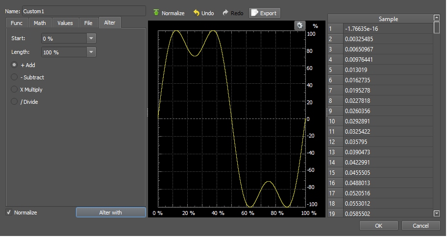
Click “Alter with” again, and repeat the process with “sin(2*PI*X*5)/5”
Adding “sin(2*PI*X*7)/7” yields:
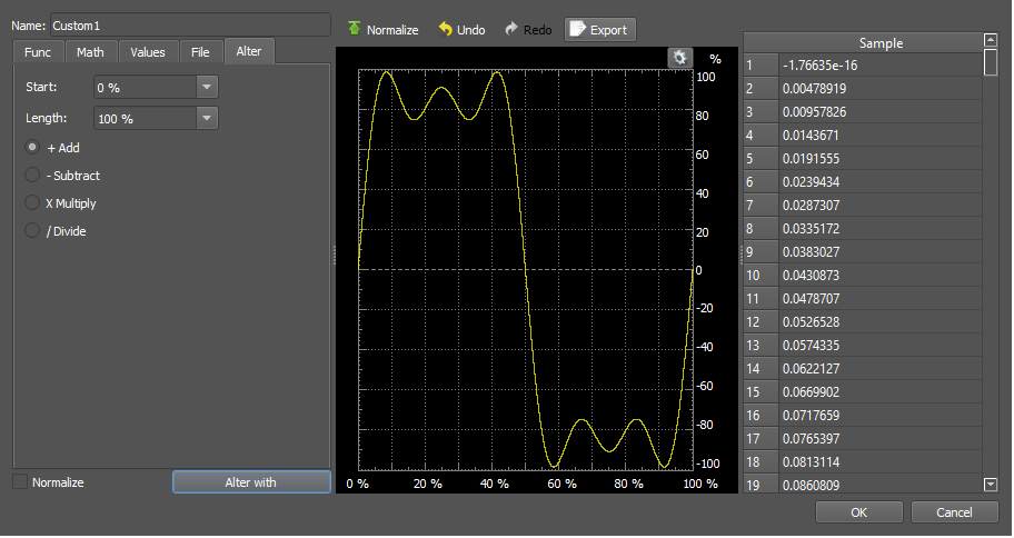
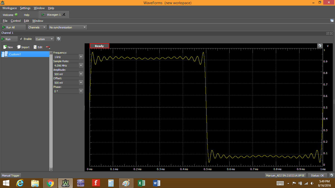
Repeating this process to the 20th iteration (sin(2*PI*X*39)/39), you can see the square wave really taking shape.
Once you click “OK” on the last editor window, your new waveform will populate in the main wavegen window.
Free Hand
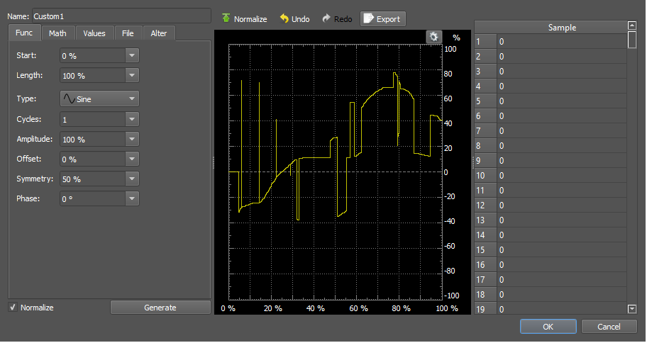
The actual last custom option is the ability ti just free hand whatever custom waveform you feel like making. Once you open the custom edito window, no matter which tab you have selected, you can simply click on the plot in the middle of the window and start drawing. Standard Cartesian plot rules apply, so only one y value per x value. Otherwise, go nuts.
If you don't like what happens, simply click “Undo”. Nice and easy!
Step 7: The Configuration Pane: Play
“Play” lets you import and playback a saved file, including audio files. Formats that can be imported include *.csv, *.txt, *.mp3, *.wav, *.wmv, & *.avi. As a point of information, the maximum number of samples that the buffer can hold is 10,000,000. Different files will have different default playback frequencies, so it's hard to say exactly how much time that would be. I had an .mp3 music file max out the sample buffer, and at 44.1 kHz playback frequency, it lasted for about 3 mins, 46 s (10 Msamples / 44.1 kHz ≅ 226 seconds). Higher definition audio will have a higher default playback frequency.
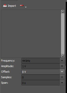
On the left side of the “Play” window you'll have some control options, most of which are blacked out until you import a file.
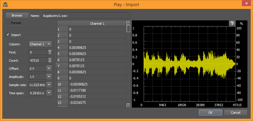
Click on “Import” to select a file to import from your computer hard drive. When you select a file, a window will open.
On the left are some options that can be edited. “Column” doesn't do much, so ignore it. “First” lets you determine what sample will be the first sample to play. “Count” is the total number of samples in the file. You can play around with “First” and “Count” to edit sample playback length. “Offset” allows you to move the vertical center of the file. It won't affect playback on a speaker, but it may affect the performance of a circuit that depends on whether a signal is +/-. “Amplitude” allows you to increase volume on a speaker. “Sample rate” is the rate at which the file samples will be played back and defaults to match the data from the imported file. “Time span” shows how long your file will play, given the number of samples to be played and the sample rate. Adjust “First” or “Count” and “Time span” will automatically adjust to match. Adjust “Sample rate” and “Time span” will also automatically adjust, and vice versa.
The Channel column in the middle is a table of every single sample. These values cannot be adjusted.
On the right you will see a plot of the waveform of your file.
Click “OK” to finalize the file import.
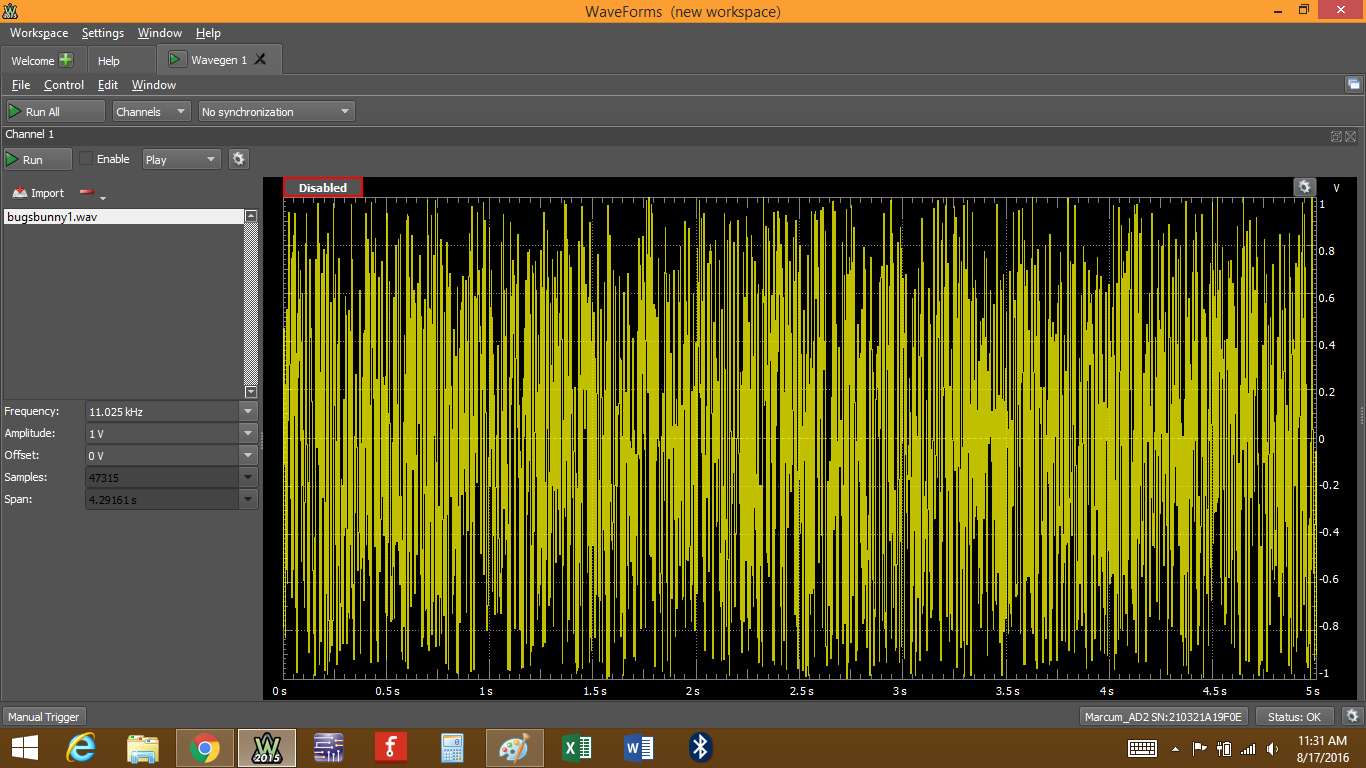
Once you have a file imported, the file appears on the left, the waveform appears on the plot, and the playback control options unlock.
You can adjust the playback frequency, offset,, or amplitude. Don't forget the default playback frequency or you'll never get back to it! Adjusting “Frequency” will automatically adjust “Span”, which is the total playback time in seconds.
Clicking on “Run” will turn on the wavegen. The signal will play through the wavegen channel wire on the 30-pin wire harness, but also through the headphone jack on the Analog Discovery 2. Wavegen channel 1 plays on the right audio channel, and wavegen channel 2 plays through the left. The wavegen channels are always available through the headphone jack, not just when “Play” is selected.
To remove a file, click on the red subtract button. You can remove one at a time or select “Clear” to remove all files.
Step 8: The Configuration Pane: Sweep
“Sweep” is used to play a range of frequencies and amplitudes within a set amount of time. The function is used in conjunction with a Network Analyzer to determine how circuits perform in the frequency domain.
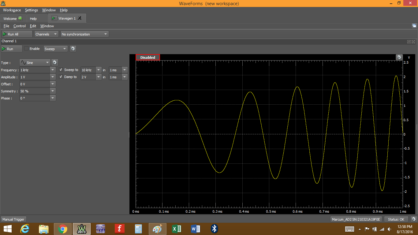
On the left you have the controls. They are the same as the controls for the “Simple” option, but with the addition of “Sweep to” and “Damp to” controls just to the right. For a walk through of the “Simple” functions, take a look back at Step 4.
“Sweep to” gives you an upper limit for your sweep range, with the lower limit set at the frequency listed in the “Frequency” box listed to the left. The time box lets you decide how long it will take to sweep up to the upper limit. Unchecking the box will keep the output at the set frequency with no sweep.
“Damp to” sets a maximum amplitude that the output can reach. The signal peak will always fall between this value and the “Amplitude” value on the left. Unchecking this box keeps the amplitude at the set value on the left for the entire sweep.

Clicking on “Run” will place the output in continuous playback. This is a fun option, so play around with it.
Step 9: The Configuration Pane: Modulation
“Modulation” allows you to modify the amplitude, frequency, or even both, of a high frequency carrier signal according to the amplitude second, lower frequency signal. You most often see signal modulation in radio frequency applications, but you can modulate any signal with any frequency down to, but excluding, DC signals. For more on how signal modulation works, check out the Wikipedia articles here for amplitude modulation and here for frequency modulation.
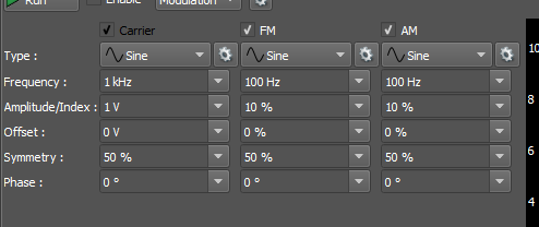
On the left you have your signal controls.
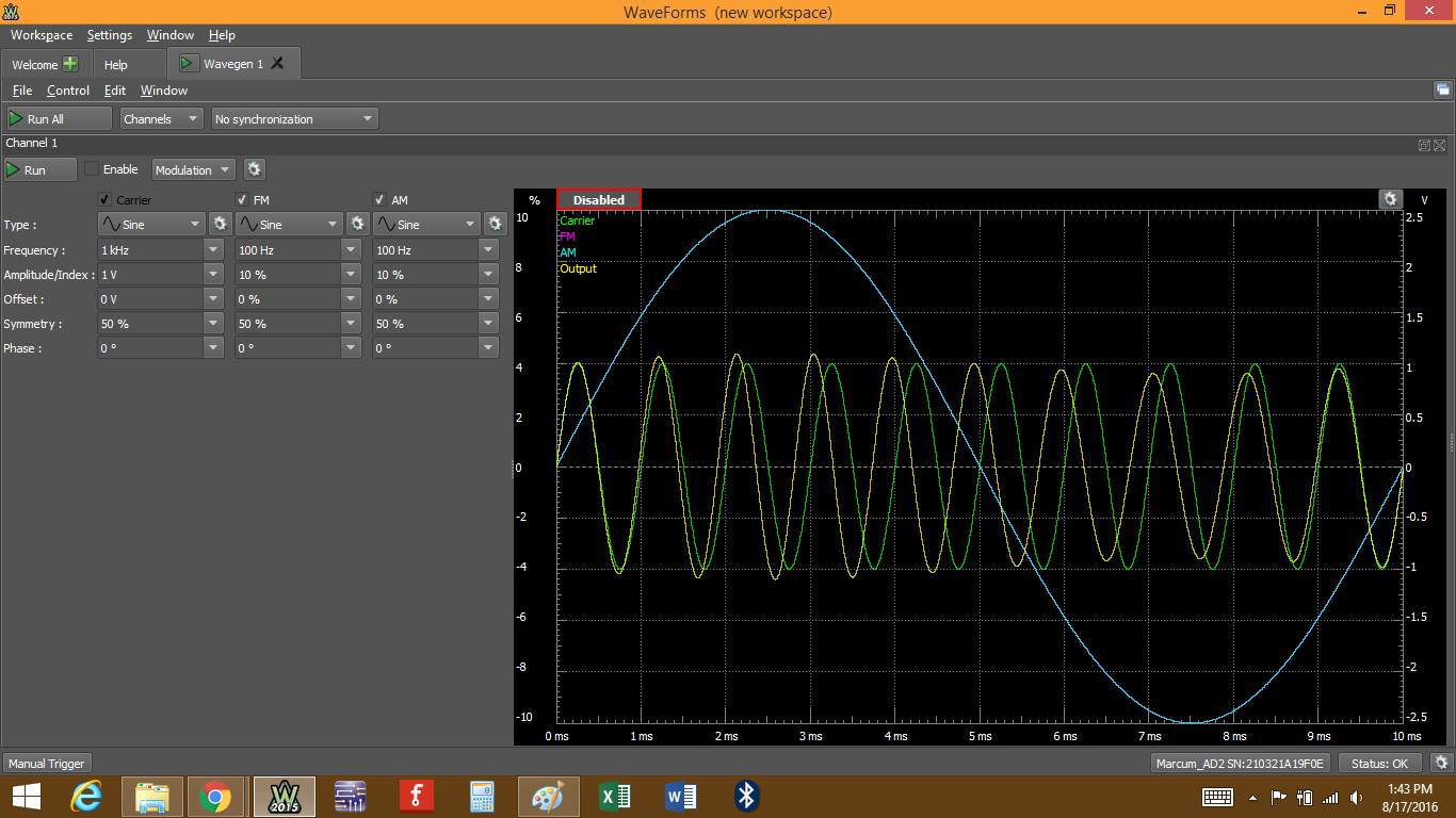
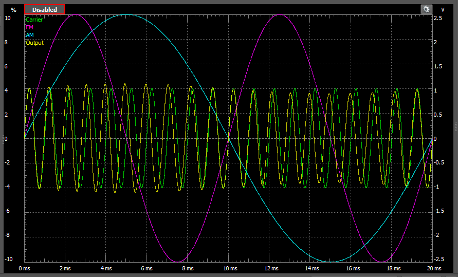
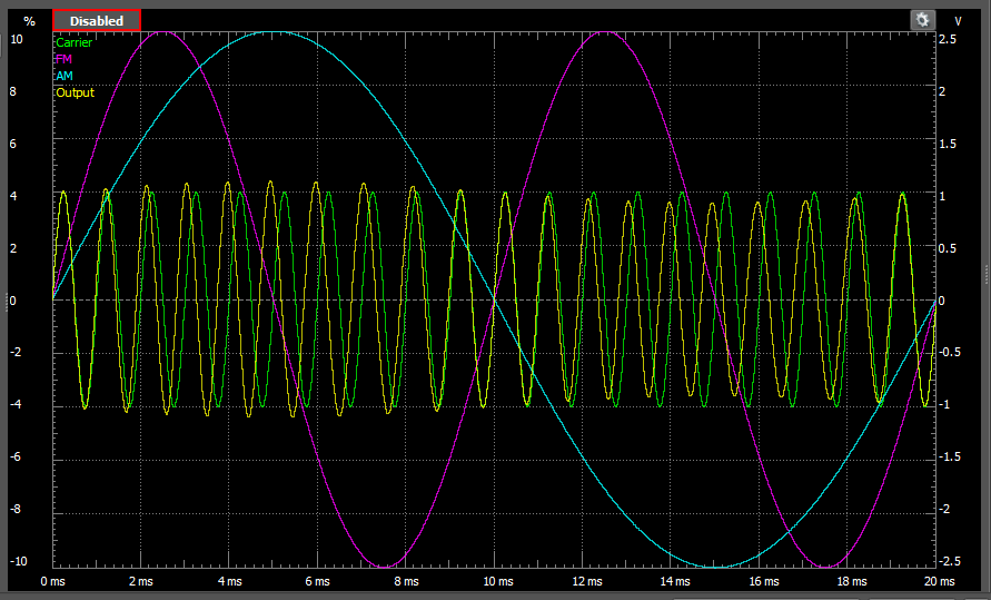
On the right you see the plot of the carrier, AM and FM modulation signals, and the final output signal.
By default, the FM and Am signals are the same, so they overlap on the plot and you can only see the trace. The AM signal was decreased to 50Hz to capture it for the image. The “output” trace is the only signal that will be generated by the wavegen, but the plot shows all signals to help you visualize the behavior of the modulated carrier.
The first set of controls is for the carrier wave and they match the controls from the “Simple” option. (For a walk through of the “Simple” functions, take a look back at Step 4.) To the right of the carrier controls, you have separate controls for frequency modulation and amplitude modulation. Unchecking the box at the top of the controls will turn off that particular set of controls.
The first parameter is the signal type. You can choose whatever type you want, including any custom signal from “Custom” or any imported signal from “Play”.
Next is the frequency of the signal. Note that by default the carrier is a full order of magnitude higher than either the FM or AM frequencies. Try to maintain this difference between the carrier signal and either modulation signal. If you are using a modulation frequency that varies, like an audio file, set the carrier to at least 10X higher frequency than the highest expected frequency from the file. Setting the carrier to less than 10X higher than the modulation frequency will result in distortion of and loss of data from the modulation signal.
Below is “Amplitude/Index”. Amplitude applies only to the carrier, and Index applies to both the AM and FM signals. Index tells you how much the AM/FM modulation signals affect your output signal relative to the carrier signal. For example, if you set the carrier frequency to 1 kHz, an index of 10% will increase the output frequency to 10% faster (1.1 kHz) than the carrier when the FM signal reaches maximum amplitude. If you set the carrier amplitude to 1 V, an index value of 20% will increase the output amplitude to 20% more (1.2 V) than the carrier when the AM signal reaches its maximum amplitude. As either modulation signal reaches its minimum value, the associated output value will be decreased by its associated index percentage.
“Offset” moves the signal vertically. “Symmetry” changes different signals in different ways, but can have some interesting effects. “Phase” shifts the signal horizontally along the time axis. All of these functions affect the carrier, AM, and FM signals in the same ways. I will leave it up to you to see how the modified AM and FM signals affect the output after playing around with some of these settings. You can get some pretty cool outputs.
Once you have it all set, simply click “Run”.
For a fun application of how to use both frequency and amplitude modulation in a circuit, check out this Instructable.
Step 10: The Preview Plot
The preview plot is on the right side of the wavegen window and will show the expected waveform output for the current wavegen option chosen.
The gear icon at the top right gives you access to the plot window parameters.

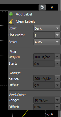
You can add a label or clear all labels with the respective button. Once you add a label, simply hover your mouse cursor over it and click and drag it where you want it on the plot. Labels will only appear on this plot.
- “Color” lets you change the plot background between black and white. The trace colors will adjust automatically to provide the best contrast with the background.
- “Plot width” lets you pick how wide the plot trace is.
- “Scale” gives you three options for scaling the plot window:
- “Auto” adjusts the window automatically to best fit the chosen signal.
- “Full” lets you adjust the time scale but auto adjusts the voltage scale.
- “Manual” lets you adjust both the time and voltage scales to get the best view of your signal.
At the bottom of the plot parameters window you will see the “Modulation” box. These parameters are only available when “Modulation” is selected from the options drop down menu because the “Modulation” plot window adds a second vertical scale on the left side of the plot the relates to the Index percentage value.
The modulation scale adjustment works just like the time or voltage scales, just in units of %.
Step 11: Now go and Play!
As you can see, the Waveform Generator with the Analog Discovery 2 and WaveForms 2015 software is very versatile. You can generate just about any type if signal you can possibly imagine.


