This is an old revision of the document!
Analog Discovery 2 - Using the Waveform Generator
Waveform generators are used to test circuits by generating defined signals that are then fed into the circuit under analysis. You can have an arbitrary waveform generator (AWG) that outputs whatever waveform the user has defined, or you can have a function generator that outputs predefined signals like sine, square, etc. The waveform generator on the Analog Discovery 2 along with WaveForms 2015 software is a combination of both generators. The Analog Discovery 2 is also small, compact, and extremely affordable compared to many generators that can cost hundreds or even thousands of dollars.
Inventory
-
- You may also use the Analog Discovery legacy or the Electronics Explorer Board with WaveForms 2015. There are some slight differences in functionality between the Analog Discovery Legacy, Analog Discovery 2, and the Electronics Explorer Board, but nothing that will prevent you from following along if you have one of the other tools.
- A computer with USB port to run the software
Step 1: The Waveform Generator
There isn't much to cover as far as background material for a waveform generator, so let's get started. If you want some help getting your device calibrated, or installing WaveForms 2015, check out this quick start Instructable collection.
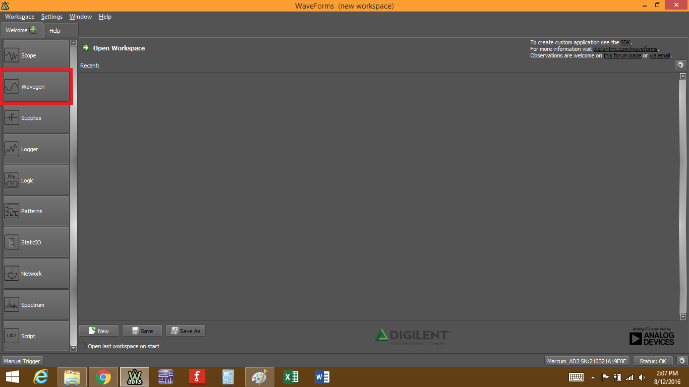
Once you have your Analog Discovery 2 and WaveForms all set up, open the waveform generator by clicking on the “Wavegen” button.
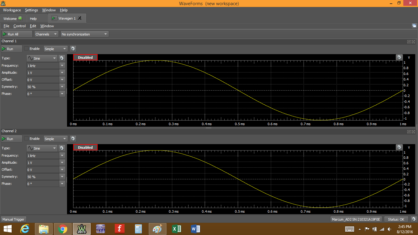
The waveform generator tool will open.
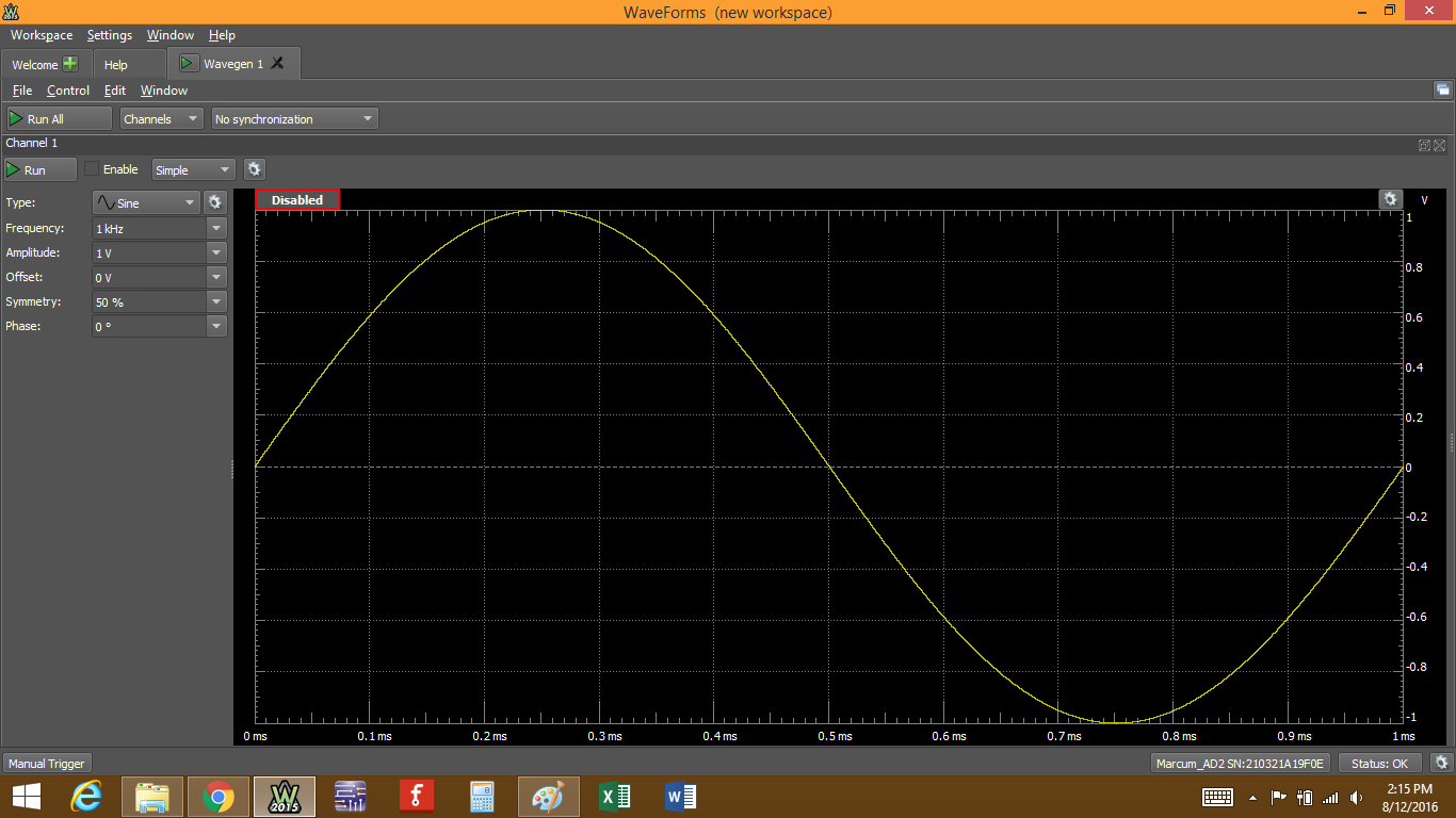
There are three main areas to pay attention to:
- The control toolbar
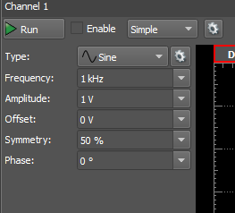
- The configuration panels, which will change based on the type of waveform you want to generate.
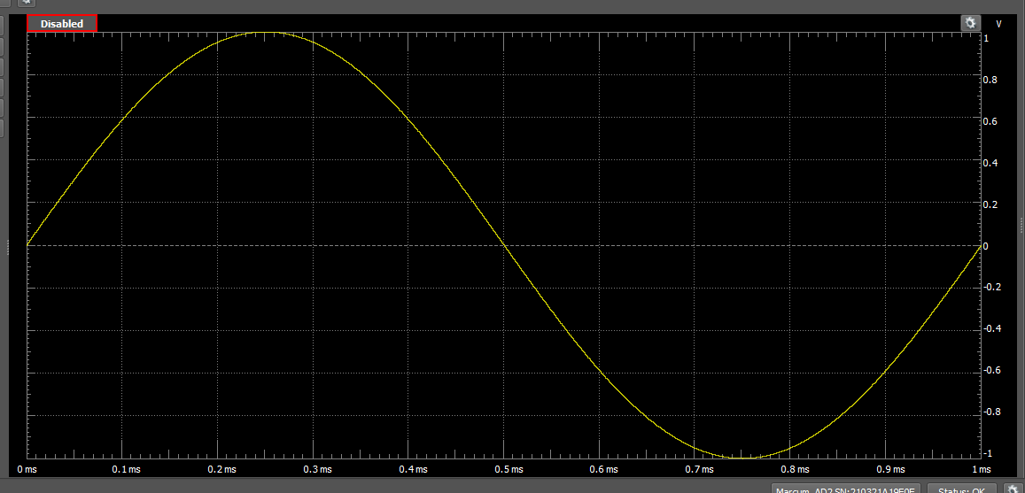
- The preview plot
Let's take them one at a time, starting with the control toolbar.
Step 2: The Control Toolbar
There are only a few controls associated with the control toolbar.

- “File” lets you open a New Wavegen instance, Open or Save a project, or Export the current wavegen data, either as an image or as a raw data file formatted in *.csv, *.txt, or *.tdms, which is specific to National Instruments.
- “Control” provides acces to the Run All and Stop All actions, which will turn on or off all enabled wavegen channels.
- “Edit” lets you copy and swap channels from one to the other.
- “Window lets you switch between different waveforms windows that are open, or access the Waveforms Help window.
- Below that, you will find the “Run All” button. This will control the function generation on all channels that have been turned on, even overriding the “Enable” box (more on that in the next step). Channels can be opened/closed from the “Channels” drop-down button next to it. All channels that have a check mark have been opened and can be viewed in their own separate pane.
Clicking on the “No synchronization” button gives you some synchronization options between the different channels and allows you to edit different trigger options. This is useful when you need to run multiple signals through the same circuit, or have one or both channels trigger at a specific time. For most applications, the default is usually appropriate.

In “no synchronization mode, no synchronization or trigger parameters are available.
In “Independent” mode, the channels are working independently. The trigger-wait-run-repeat settings can be independently configured for each channel and opened in each channel's specific pane. If you modify the trigger settings of a channel, its signal generation starts over from the beginning and synchronization with the other channels is lost.
In “Synchronization” mode, the trigger-wait-run-repeat settings are the same for all selected channels within the same instrument instance. Modifying the settings of one of the channels causes both to be restarted. A run time value other than continuous should be used to periodically re-synchronize the channels. This has to be done because the actual frequencies might be approximates of the desired values and small errors accumulate until, after several cycles, the channel's phase will slide.
The “Auto” synchronization mode is similar to the “Synchronized” mode where run time is automatically adjusted to the longest period from all channel's settings (depending on signal frequency sweep/damp time, or AM/FM modulator frequency).
For the trigger settings, the button displayed below in Fig. 9 lets you determine what type of trigger source you want. You can select “none”, or use some external signal, or even one of the Waveforms tools, like the Oscilloscope. You can also trigger the signal manually by setting the trigger to “manual” and then clicking on “Manual Trigger” in the bottom left corner of the window.


