This is an old revision of the document!
Lab 7a: Digital Signal Generator
Download This Document
1. Objectives
- Use a programmable IIR filter to generate a single frequency sine wave.
- Use PWM to generate an audible output tone over the Basys MX3 speaker.
- Display the frequency of the synthesized sine wave on the LCD and 7-segment display.
2. Basic Knowledge
- How to display text on a character LCD
- How to display numbers on the 4-digit 7-segment display
3. Equipment List
3.1. Hardware
- Workstation computer running Windows 10 or higher, MAC OS, or Linux
In addition, we suggest the following instruments:
3.2. Software
The following programs must be installed on your development work station:
- WaveForms 2015 (if using the Analog Discovery 2)
4. Project Takeaways
- How to implement digital filters in C using a PIC32 microprocessor.
- How to use the PIC32 processor to make a signal generator.
- How to create analog output using pulse-width modulation.
- How to use change frequency of synthesized signals.
5. Fundamental Concepts
5.1. IIR Digital Filters
As introduced in Unit 7, an infinite impulse response (IIR) digital filter can be mathematically expressed by Eq. 5.1 below. Zeros of the transfer function, H(z), are the roots of the numerator polynomial. Poles of the transfer function are the roots of the denominator polynomial. We will use specific placement of the poles and zeros to cause the output to ring or oscillate indefinitely at specific frequencies.
$$H(z) = \frac{Y(z)}{X(z)} = \frac{\sum_{i=0}^{M-1} b_i \cdot z^{-i}}{\sum_{k=0}^{N-1} a_k \cdot z^{-k}} = \frac{b_0 + b_1 \cdot z^{-1} b_2 \cdot z^{-2} + \cdots b_{M-1} \cdot z^{-M-1}}{a_0 + a_1 \cdot z^{-1} a \cdot z^{-1} + \cdots a_{N-1} \cdot z^{-N-1}} \qquad (\text{Eq. 5.1})$$
From a table of Z transforms, the z transform of a sine wave is a second order IIR filter that is expressed by Eq. 5.2. It has two complex poles at $e^{±j2 \pi Fo/Fs}$ and two zeros at the origin.
$$H(z) = \frac{\sin(2 \pi f_0 /F_s) \cdot z^{-1}}{1-2 \cdot \cos \bigg( \frac{2 \pi f_0}{F_s} \bigg) \cdot z^{-1} + z^{-2}} = \frac{Z_1 \cdot z^{-1}}{(1-p_0 \cdot z^{-1}) \cdot (1-p_1 \cdot z^{-1})} \qquad (\text{Eq. 5.2})$$
5.2. The Z-plane Unit Circle
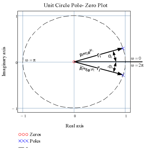
The z plane is a unit circle that describes a surface of complex numbers using polar coordinates. Poles and zeros are the roots of the denominator and numerator polynomials, respectively expressed in Eq. 5.1 or Eq. 5.2. These roots can be represented in the frequency domain as a vector, as shown in Fig. 5.1 and expressed by Eq. 5.3. The variable r represents the magnitude of the vector and the angle Θ represents the frequency normalized by the sampling frequency, expressed in radians.
$$p_{0,1} = r_i \cdot e^{\pm j0_i} \qquad (\text{Eq. 5.3})$$
 Figure 5.1. Complex poles plotted on the z-plane for the 7500 Hz sine wave oscillator.
It is beneficial to understand how the pole-zero plots on the z-plane are representations of digital filters. To explain it in a single sentence, digital filters can be written as transfer functions in the form of Eq. 5.2, the poles and zeros of which can be expressed in the frequency domain as a vector. Figure 5.1 illustrates the set of complex poles for the transfer function of a sine function at 7500 Hz when the sampling frequency, Fs, is set to 160000 Hz. Since the digital filter design process generates a unique polynomial, the placement of the poles and zeros in the z-plane are equally unique. Zeros on the unit circle will cause the numerator of the transfer function to be zero, causing the filter to output a zero amplitude signal when excited at the frequency, ω, corresponding to the angle Θ. Zeros at the origin contribute nothing to the dynamics of the transfer function.
In contrast, poles on the unit circle cause the denominator of the transfer function to equal zero, hence the output of the filter will be infinite and it will oscillate indefinitely when excited at the frequency, ω, corresponding to the angle Θ. Poles outside the unit circle indicate that the filter is unstable and the amplitude of the oscillations will increase toward infinity. Poles just inside the unit circle will cause the filter to oscillate; however, the amplitude is bounded (fixed maximum). We will take advantage of this characteristic to make the eight oscillators used in Lab 7a.
The poles in Fig. 5.1 are those represented by blue X’s and the zeros by red circles. Note that the poles and zeros that do not lie on the real axis exist in complex conjugate pairs. The z-plane frequency, ω, relates to the real-world signal frequency by noting that ω = π for f = the Nyquist rate, which is half of the sampling rate in samples per second.
5.3. An IIR Digital Oscillator
Although as References 6 and 7 prove the recursive filter signal generation using the fixed point math approach is not novel, it does offer significant memory and computational efficiency over the commonly used table look-up methods and algorithms based on trigonometry functions. The Timer2 ISR for the IIR approach to signal generation requires 1.6582 μs of the 6.25 μs PWM period, resulting in 26% CPU time loading. The gen_tones IIR function requires only 364 bytes of program memory and 24 bytes of data storage. Although the table look-up method requires minimal program memory, to achieve the same degree of resolution will require 160 K bytes of data storage memory. Table look-up methods can use fixed point mathematics. The look-up tables themselves use floating point sine functions when generated during an initialization, but only to that extent. The function method uses the sine trigonometric function to generate the output in real time. Since the trigonometric function method uses floating point math throughout the signal synthesis process, it is confined to low frequency applications. However, this method does offer the highest degree of resolution.
From the previous discussion, we can generate an oscillator of any frequency between zero and half the sampling frequency by using Eq. 5.2, or by placement of the poles in Eq. 5.3. In either case, the desired oscillator transfer function is computed using Eq. 5.4. Since the input to the digital filter is a unit impulse, it only exists for the computation of the y[1] output, which can be set as the digital filter initial condition without the need for an input signal at all.
$$y[ n ] = -a_1 \cdot y [ n-1 ] - a_2 \cdot y [ n-2 ], \text{with} a_1 = -\cos \bigg( \frac{2\pi F_0}{Fs} \bigg), a_2 = 1, y [ 1 ] = \sin \bigg( \frac{2\pi F_0}{Fs} \bigg), \text{and} y [ 0 ] = 0, \text{for} n > 1 \qquad (\text{Eq. 5.4})$$
The C program functions shown in Appendix A provide code to create a sine wave at 5000 Hz. Listing A.1 defines the global constants and declares the public functions and variables. Listing A.2 initializes the audio output for the defined 5000 Hz oscillator and is called from the main function infinite loop. The filter coefficients for the default 5000 Hz IIR filter are configured here for convenience. The variable tones_active is set in Listing A.3 and starts the oscillator and is reset in the main function loop to stop the oscillator.
Listing A.3 provides for the capability to generate different frequencies using a common IIR filter algorithm shown in Listing A.4. Since the oscillator is started with an impulse input, the outputs are initialized to start with the pre-computation of y[n-1], as shown in Eq. 5.4. The function in Listing A.3 is called to start the oscillator output.
The function shown in Listing A.4 is called from the Timer 2 ISR shown in Listing A.5 at the PWM period rate if the tones_active variable is set TRUE.
6. Problem Statement
You are to create a digital sine wave generator capable of synthesizing eight constant amplitude signals at frequencies specified in Section 8.1. The frequency of the sine waves will be selected by setting one of the eight slide switches. The audible output will be enabled and the frequency displayed on the 4-digit 7-segment display for five seconds when BTND is pressed. The LCD will display the frequency of the selected sine wave.
7. Background Information
See the discussion of IIR filters in section 6.3.2. of the Unit 7 text.
8. Lab 7a
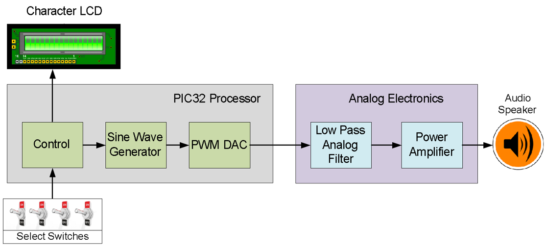
The objective for this lab is to create a programmable digital oscillator as modeled in Fig. 8.1.
8.1. Requirements
- The peripheral bus clock is to use a divisor of 1 (set in config_bits.h).
- The PWM period is to be set for 160000 Hz. (This PWM period was selected to take advantage of the analog low-pass filtering of the PWM output to produce a clean sine wave shown in Fig. 8.4.)
- The eight Basys MX3 slide switches are set to generate a single frequency tone as listed in Table 8.1.
- When BTND is not pressed, the LCD will display as shown in Fig. 8.2.
- When BTND is pressed, the LCD will display as shown in Fig. 8.3 and output the tone selected for 5 seconds.
- The frequency of the 8 synthesized tones are to be measure using the Analog Discovery 2, as shown in Fig. 8.4, and added to Table 8.1 as shown below. The analog signal trace shown in Fig. 8.4 was captured using the MIC analog input. No code is required because the MIC on the Basys MX3 board is picking up the speaker audio. The amplitude of the signals you capture may differ from Fig. 8.4 because of the MIC Volume and Speaker Volume potentiometer settings.
- Record amplitudes of the sine wave for the 8 tones without modifying the MIC Volume and Speaker Volume settings.
- Record the 8 sets of filter constants for the frequencies listed in Table 8.1.
 Figure 8.1. Block diagram for Lab 7a.
Table 8.1. Frequency Select.
| On Switch | Osc. Frequency | IIR Filter Coefficients | Peak Amplitude | Measured Frequency | Frequency Error | ||
|---|---|---|---|---|---|---|---|
| a0 | a1 | a2 | |||||
| SW0 | 500Hz | ||||||
| SW1 | 1500Hz | ||||||
| SW2 | 2500Hz | ||||||
| SW3 | 3500Hz | ||||||
| SW4 | 4500Hz | ||||||
| SW5 | 5500Hz | ||||||
| SW6 | 6500Hz | ||||||
| SW7 | 7500Hz | ||||||
