This is an old revision of the document!
Cmod A7 XADC Demo

Overview
A project that instantiates the XADC IP Core and measures an analog voltage.
Features Used
| Not Used | Used | |
|---|---|---|
| 2 user LEDs | X | |
| 1 tri-color LEDs | X | |
| 2 User Push Buttons | X | |
| 48 GPIO Pins | X | |
| 1 Pmod port | X | |
| Pins for XADC signals | X | |
| USB-UART Bridge | X | |
| 512 kB SRAM | X |
Description
This simple XADC demo is a verilog project made to demonstrate the ADC functionality of the Cmod-A7's Analog to Digital Converter.
- The RGB LED brightens the RED LED when the read voltage goes up.
- When BTN1 is pressed, the demo switches which xadc pin to read from.
This demo uses XADC ports 4 and 12 since they are the channels connected to pin 15 and 16. This can be seen in the Cmod A7 Reference Manual and Schematics. These resources can be found on the Cmod A7 Resource Center.
Prerequisites
Hardware
- Cmod A7 FPGA board
- Micro-USB cable
- Breadboard
- Resistors
- Wire
Software
- Vivado Design Suite 2016.4
- Newer versions can be used, but the procedure may vary slightly
- Digilent Board Support Files for Vivado
- Follow the Vivado Board Files for Digilent 7-Series FPGA Boards guide on how to install Board Support Files for Vivado.
Downloads
Cmod A7 15T XADC Project Repository – ZIP Archive GIT Repo
Cmod A7 35T XADC Project Repository – ZIP Archive GIT Repo
Download and Launch the Cmod A7 XADC Demo
1) Follow the Using Digilent Github Demo Projects Tutorial. This is an HDL design project, and as such does not support Vivado SDK, select the tutorial options appropriate for a Vivado-only design. You can launch the demo as soon as you have generated a bitstream, so you do not need to return to this guide when prompted to check for extra hardware requirements and setup.
Important
Make sure that between the 15T and 35T versions of the project, you download the version that applies to your Cmod A7.
Using the Cmod A7 XADC Demo
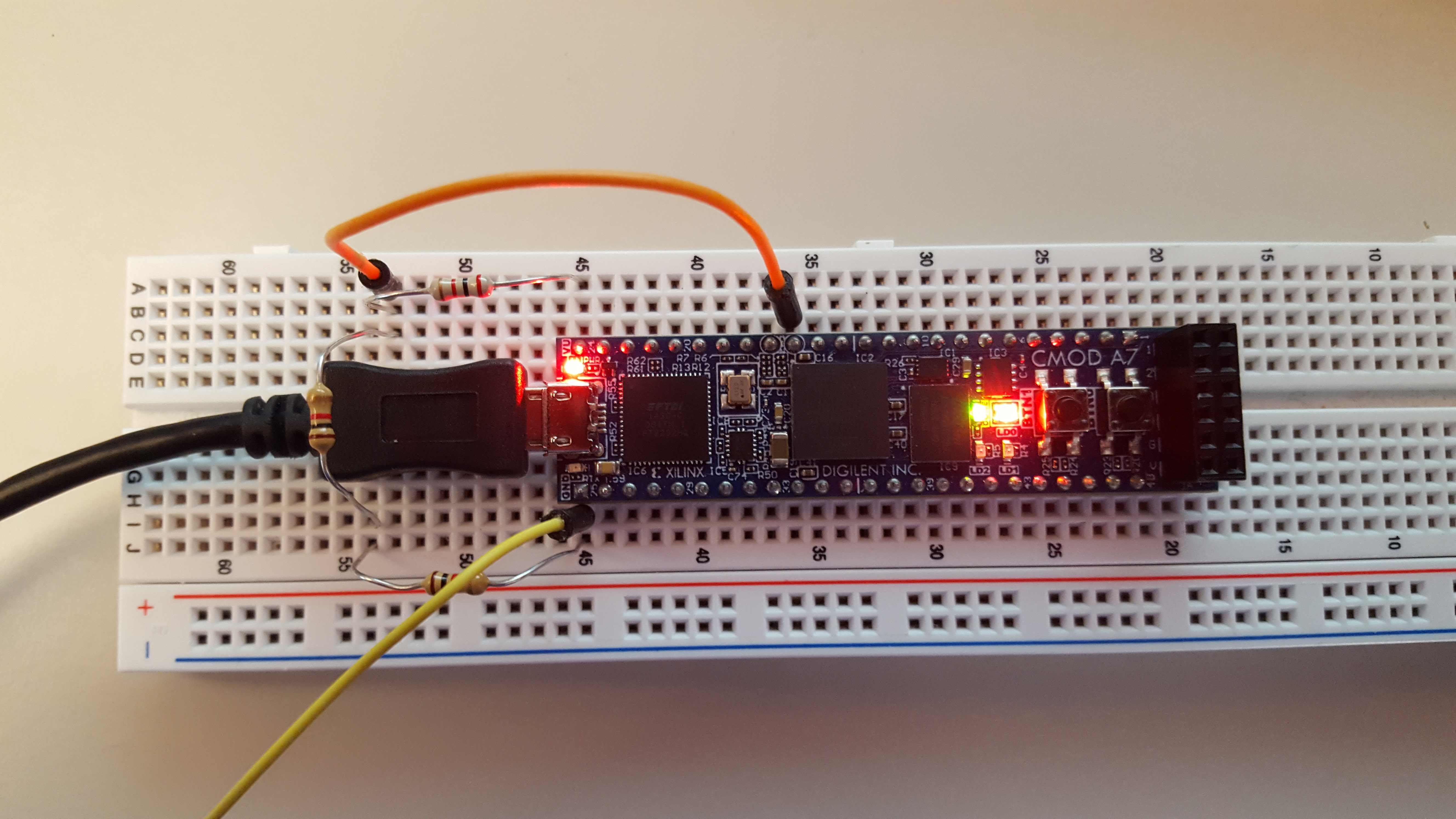
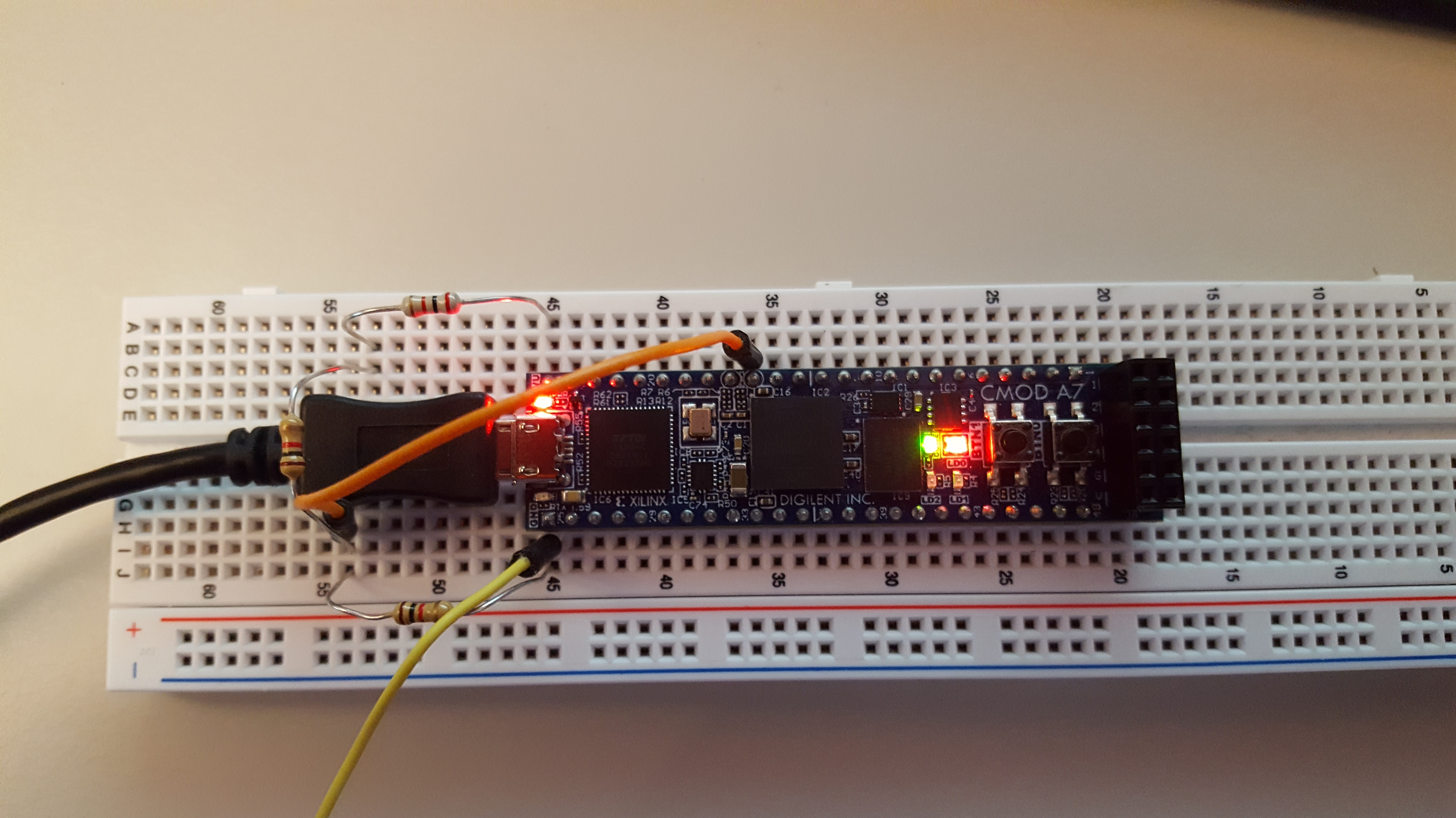
The demo reads analog data in from pin 15 and sets the brightness on the red led linearly. The pictures below used a resistor ladder to show the different brightness values the demo puts out. This demo can be used to measure any voltage between 0 and 3.3 volts. The brighter the led, the closer to 3.3 the voltage is. The voltages below are 2.3V, 1.1V and 0V.