Debouncing With the NE555 Timer IC
Introduction
In previous projects, we have debounced button inputs in a variety of ways; from software, analog circuits, and integrated circuits. In this project, we will be adding another integrated circuit that can be used to debounce inputs. The IC that we will be using is the 555 timer IC, which has many more uses than just debouncing.
Prerequisites
- Understand debouncing.
- Understand how to wire an IC.
- Understand how a capacitor works.
Inventory
- 2 LEDs
- 1 Button
- 3 220Ω resistors (red, red, brown)
- 1 10kΩ resistor (brown, black, orange)
- 2 10μF electrolytic capacitors
- 1 0.01μF (10 nF) Ceramic Capacitor
- 1 555 Timer IC
Monostable Circuits
A monostable circuit is a circuit where only one of the states is stable (doesn't change without trigger), and the other state (unstable state) changes back to the stable state after a set time. It is this property that will make it possible to debounce the button, since once triggered, it can't be re-triggered until after it resets for the set time.
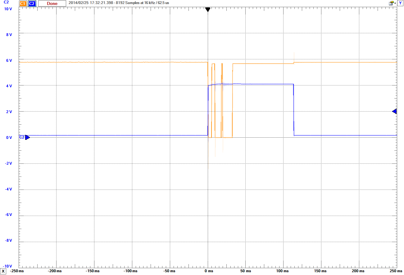
Figure 1 below shows the basic behavior of the output of a monostable circuit with a bouncing input. Figure 2 is the scoped monostable circuit using a 555 timer, showing the same action. The main takeaway from both of these figures is that monostable circuit is triggered by the first spike and bounce spikes are ignored; this happens because a monostable circuit outputs HIGH for a set amount of time, and thus will ignore any bounces that occur during that time frame.
We have been saying that the monostable circuit outputs for a set amount of time. However, the time is determined by how long it takes to charge a capacitor to a certain voltage. We will discuss how to find this charging time in the next section.
555 Timer Overview
The 555 timer IC has found widespread use in a variety of applications, and is still used widely due to how easy it is to use as well as its low price. The basic 555 timer IC included in the chipKIT Starter Kit is the NE555. There are several different part numbers that are 555 timers, and most of them are similar enough to ignore the differences, but check the data sheet for the particular limitations.
We'll start by listing the 555's pins and a brief description of that pin's function.
- GND:This pin should be connected to the circuit ground.
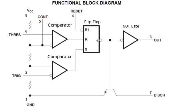
- TRIG:This pin sets the internal flip-flop so that the DISCH pin is disabled and the output pin is LOW. It is triggered when the voltage level is 1/3 or lower than Vcc.
- OUT:This pin is the timer's output, it outputs either HIGH or LOW.
- RESET: When this pin is pulled LOW, it resets the timer by pulling the output LOW and enabling DISCH.
- CONT: This pin has a specialized use, since it gives direct access to the compared voltage level for THRES and indirectly change the voltage level for TRIG.
- THRES: This pin resets the internal flip-flop which enables the DISCH pin and sets the output pin to HIGH. It is triggered when the voltage level is 2/3 or higher than Vcc, or the voltage level of the CONT pin.
- DISCH: This pin is used for automatic discharging when the output is HIGH. This pin is often used to discharge the capacitor.
- Vcc: This pin should be connected to the voltage supply rail. This sets the default voltage levels for the comparators.
The 555 Timer: Monostable Mode
We will discuss the general layout of the circuit for the 555 timer's monostable mode. The timing aspect of the circuit will be calculated below. Figure 4 below shows how the 555 should be wired to get monostable behavior from it.
The way this circuit works is when the input pin (pin 2) is pulled LOW, it disables the DISCH pin (pin 7) and allows the capacitor connected to pins 6 and 7 to charge through resistor (RA). Once the voltage across the capacitor is at or above 2/3 VCC, the THRES pin (pin 6) enables DISCH which discharges the capacitor back to 0V.
There are many different ways to wire the 555 timer to alter the behavior. There are three primary modes that a 555 timer is configured to be in, but there are some specialized uses that it can be used for: the three primary modes are monostable, bistable, and astable.
- Monostable mode stays LOW and when triggered, it temporarily goes HIGH for a some time and then back to LOW.
- Bistable mode changes mode to the pin that gets triggered. There are no capacitors and no timing since only two pins are used. RESET and TRIG are used to set and reset the OUTPUT to LOW or HIGH. Which is how this mode gets the name bistable, since both states are stable.
- Astable mode constantly changes between LOW and HIGH. The timing of the HIGH state and LOW state depend on the resistors and capacitors and how they are wired together.
Pulse Time Calculation
We are going to get into some slightly advanced mathematics in this section to explain how we arrive at the following equation for how long the pulse will be.
&&t \approx 1.1 R C$$ The first thing to consider before writing down equations is to understand how the 555 timer determines when to reset. In the previous section we discussed the pins. The circuit layout (shown above in Fig. 4) has two pins in between the resistor and capacitor that determine the time constant. These pins are the THRES and DISCH pins. Once the THRES pin reaches $2/3$ supply voltage the DISCH pin is enabled, which discharges the capacitor and resets the timer. This means that the resistor and capacitor determines how long the output will be HIGH before resetting.
Since this is a simple charging capacitor, we can use the equation:
$$V(t) = V_0 (1-e^{-t/\tau})$$
We'll start by dividing both sides by $V_0$, with $V(t)$ equal to $\frac{2}{3} V_0$.
$$\frac{V(t)}{V_0} = \frac{(2/3) V_0}{V_0} = \frac{2}{3} = 1 - e^{-t / \tau}$$
Now we'll add $(e^{-t/\tau} - 2/3)$ to both sides.
$$e^{-t/\tau} = 1 - 2/3 = 1/3$$
Now we take the natural logarithm of both sides.
$$-t/\tau = \ln{1/3}$$
Multiply both sides by $-\tau$, to get the equation in terms of t.
$$t = -\tau \ln{1/3} = \tau \ln{((1/3)^{-1})} = \tau \ln{3}$$
We did a few more steps in the above equation to simplify it. We can also use definition of the time constant $\tau$, which is $\tau = RC$. Where R is the resistance and C is the capacitance of the circuit. Also, $\ln{3} = 1.0986... \approx 1.1$, which gives us the 1.1 in the final equation.
$$t \approx 1.1 R C$$
This is how we derived the equation at the start of the section. This equation is used to either find the pulse time, or the value of either the resistor or capacitor needed to find a certain pulse time.
The resistor we'll use is one of the 10 kΩ resistor and two 10 μF capacitors in parallel (their capacitance adds together) which gives 20 μF. We plug these values into the equation to get:
$$t \approx 1.1 * 10 * 10^3 \Omega * 20 * 10^{-6} F = 220 ms$$
220 ms is long enough to prevent bounces from affecting the circuit, without being to long to be very noticeable. So we will use the 10 kΩ resistor and two 10 μF capacitors in the timing circuit of the 555 timer. How this is wired will be explained below in the circuit section.
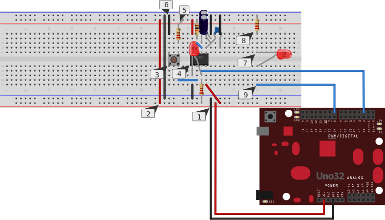
1. Setting up the Circuit
Now we will set up the circuit for this project.
- Connect 5V0 and GND to the bus strips of the breadboard.
- Connect both ground and voltage strips together.
- Place a button onto the breadboard so that it crosses the valley.
- Pin 1 is connected to the ground rail.
- Pin 2 is connected to a leg of the button.
- Pin 3 is connected to the chipKIT board's pin 2, a 220Ω resistor connected to the voltage rail, and the anode leg of an LED the cathode leg connected to ground.
- Pin 4 is connected to the voltage rail.
- Pin 5 is connected to the ground rail through the 10 nF capacitor.
- Pin 6 is connected to the 555's pin 7 and two 10 μF capacitors connected to ground.
- Pin 7 is connected to the 555's pin 6 and the voltage rail through the 10 kΩ resistor.
- Pin 8 is connected to the voltage rail.
- Connect a 220 Ω resistor from the voltage rail to the leg directly opposite to the leg that is connected to pin 2 of the 555 timer.
- Connect the other leg on the same side as the leg with the resistor to the ground rail.
- Place an LED across the valley of the breadboard.
- Connected the cathode (short) leg of the LED to the ground rail through a 220 Ω Resistor.
- Connect the anode (long) leg of the LED to pin 8 of the chipKIT board.
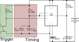
In Fig. 7 below, you'll see the circuit schematic of the 555 and the parts relevant to it. The red section is the RC circuit that determines the pulse length, and the green section is the circuit that is used to trigger the 555.
The Code
Since the debouncing is done by the circuit, we can use an interrupt to toggle an LED on or off. We will use the serial monitor to see that the chipKIT was programmed and has its interrupts triggered when the button is pressed. We will be using interrupt 1 which is tied to pin 2. The LED we will be toggling is connected to pin 8.
An interrupt functions just as the name implies. An interrupt is a signal that is sent from the hardware or software to the processor, alerting the need for immediate attention. It will create a high-priority condition that the processor will handle, interrupting the current thread being executed and temporarily suspending all other actions, saving its state before proceeding. The processor will execute an interrupt handler to complete the event before returning to its saved state.
int LED = LOW;

void setup()
{
  pinMode(8, OUTPUT);
  pinMode(2, INPUT);

  Serial.begin(9600);
  digitalWrite(8, LED);
  attachInterrupt(1, isr, RISING);
}

void loop()
{
  Serial.println("Running");
  delay(1000);
}

void isr()
{
  Serial.println("Interrupt Triggered");
  LED = !LED;
  digitalWrite(8, LED);
}


