This is an old revision of the document!
Using the Power Supplies

Introduction
This guide explains the use of the Supplies instrument in WaveForms. This instrument is used to configure a Digilent Test & Measurement Device's variable power supplies.
Prerequisites
- A Digilent Test & Measurement Device with Variable Power Supplies
- A Computer with WaveForms Software Installed
Note: This guide only pertains to the Analog Discovery 2 and Analog Discovery Studio. Other Digilent Test & Measurement devices have a different UI for their Supplies instrument.
1. Opening the Supplies Instrument
1.1
Plug in the Test & Measurement Device, then start WaveForms and make sure the device is connected.
If no device is connected to the host computer when WaveForms launches, the Device Manager will be launched. Make sure that the device is plugged in and turned on, at which point it will appear in the Device Manager's device list (1). Click on the device in the list to select it, then click the Select button (2) to close the Device Manager.
Note: “DEMO” devices are also listed, which allow the user to use WaveForms and create projects without a physical device.
Note: The Device Manager can be opened by clicking on the “Connected Device” button in the bottom right corner of the screen (3), or by selecting “Device Manager” from the “Settings” menu at the top of the screen.

1.2
Once the Welcome page loads, in the instrument panel at the left side of the window, click on the Supplies button to open the Power Supplies instrument.

1.3
Once the Supplies instrument opens, the window contains the controls for the two variable power supply rails, described in the next section.

2. Using the Supplies
This section walks through setting up the power supplies and voltmeter to measure the DC output of the power supplies
2.1 Hardware Setup
In order to measure the output of the variable power supply pins, these pins must be connected to something that can measure voltages. While a standard digital multimeter or voltmeter could be used, this guide will show how to use WaveForms' Voltmeter instrument to measure the supply voltages.
Connect the test & measurement device's positive variable supply output pin (red wire, labeled “V+”) to the device's analog input Channel 1 pin (orange wire, “1+”).
Connect the test & measurement device's negative variable supply output pin (white wire, “V-”) to the device's analog input Channel 2 pin (blue wire, “2+”).
If the test & measurement device has differential analog input channels, make sure to connect the analog input channel negative pins, labeled “1-” (orange wire with white stripes) and “2-” (blue wire with white stripes) to the device's ground (black wire, marked with a down arrow).

2.2 Software Setup
With the loopback circuit set up, WaveForms' Voltmeter instrument must be set up to report measured DC voltages.
From the Supplies tab, opened in step 1.2, return to WaveForms' Welcome page by clicking on its tab at the top of the screen. In the Welcome tab, open the Voltmeter instrument, then click the Run button ( ) in the control bar near the top of the window to begin capturing data. The DC voltage measured on each analog input channel is reported in the “DC” row of the table just below the Run button.

In order to show both the Voltmeter and the Supplies instruments on the screen at once, click on the Docking Windows button ( ) in the top right corner of the screen.
Note: To return to the default tabbed view later, click on the Tabbed Windows button ( ) adjacent to the Docking Windows button.

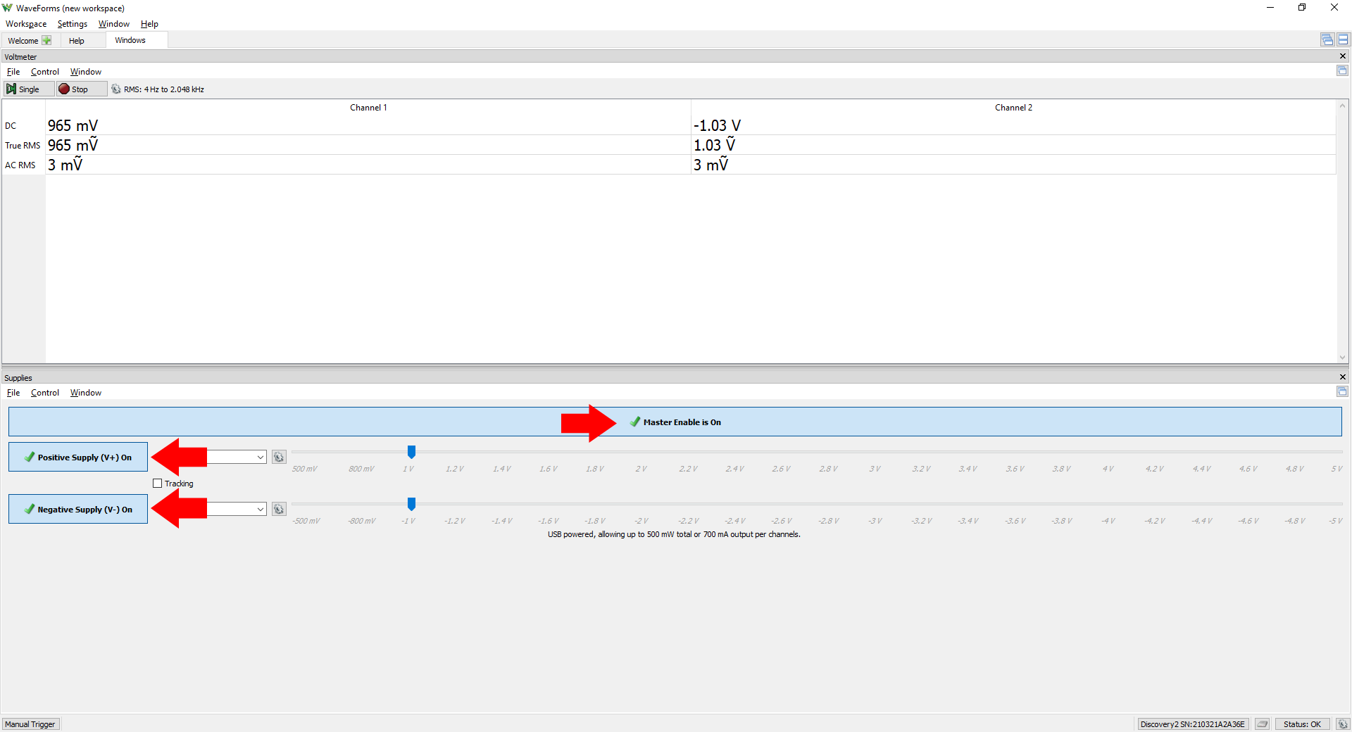
2.3 Enable the Supplies
When the Supplies instrument is first opened, the power supplies are disabled.
The “Master Enable” button can be used to switch both of the variable supplies off or on at once. The “Positive Supply” and “Negative Supply” buttons can be used to enable or disable each of the two variable supplies individually. While the Master Enable is off, each power supply can be set to a Ready or Off state, if the supply is ready, it will be turned on when the Master Enable is set to on.
Make sure that both power supplies are set to Ready, then click on the Master Enable button to turn both of them on.
3. Power Supplies User Interface Walkaround
The remainder of this guide describes the functionality of the rest of the Power Supplies user interface. While following along, experiment with power supply controls described, and look back at the Voltmeter to see how they the voltage outputted by the variable supplies is affected.
3.1 Individual Supply Controls
Each Voltage field (labeled 1 in the image to the right) can be used to set the voltage output by that supply. This field can be set by either typing a voltage value (with units) into the text field, or by using the drop-down to select a value. When a value is entered that is outside of the possible range for the test & measurement device, the value is clamped to the nearest voltage that can be output.
The output voltage level can also be changed by adjusting the slider (2) to the right of the voltage field.
The Gear button ( ) to the left of the slider allows the user to limit voltage range that can be used for both the slider and Voltage field for that channel.
As previously mentioned in step 2.3 of this guide, each power supply has its own enable/disable button (3).

3.2 Controlling both Supplies
As previously mentioned, each supply can be enabled or disabled at once using the Master Enable button.
When checked, the Tracking checkbox (located between the two channels) mirrors any changes made to the voltage output in one channel on the other. For example, if the positive supply is set to output 2V, the negative supply will automatically be changed to output -2V.
![]()
3.3 Menu Bar
The File menu, in the menu bar at the top of the supplies instrument, allows the user to save and load Supplies instrument configurations.
The Control menu exposes the same functionality as the Master Enable Button, and lists hotkeys that can be used to quickly stop and run the power supplies.
The Window menu provides a fast way to switch to other tabs open in WaveForms.

Next Steps
For more guides on how to use the Digilent Test & Measurement Device, return to the device's Resource Center, linked from Instrumentation page of this wiki.
If voltage values output by the Supplies are significantly different from expected, please calibrate the device by following the Calibration Guide.
For more information on WaveForms visit the WaveForms Reference Manual.
For technical support, please visit the Scopes and Instruments section of the Digilent Forums.