

This project designs a smart RGB lamp which is powered by a battery and controlled through an app running on a smartphone. The lamp and smartphone communicate through Bluetooth Low Energy (BLE). Besides setting the luminosity and the color of the LED, the system also measures the ambient lighting, so users can switch off the light once it is no longer needed. Or do that even automatically, if needed.
Digilent’s Analog Discovery Pro ADP3450 running in Linux Mode is at the heart of the system: it collects the data from a Pmod ALS ambient light sensor and receives the settings from the smartphone’s app through a Pmod BLE. It also applies the brightness and color of the LED based on these data sets or switches the on/off state.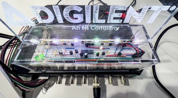
Getting a HAL for the Analog Discovery Pro
In our project, we control the Analog Discovery Pro (ADP) through the WaveForms SDK with a Python script. For this, we need several functions for each of the instruments, like read, write, initialization, and control functions. Communication over SPI (Serial Peripheral Interface) and UART (Universal Asynchronous Receiver-Transmitter) is also necessary. This means that we require some sort of abstraction to simplify the interaction with the hardware: a Hardware Abstraction Layer (HAL).
There are two ways to get the HAL functions for our project: One way is that you follow the directions given in the Getting Started with WaveForms SDK guide. The other way is that you download them from Digilent’s GitHub repository. There, you will also find a list of the functionality each module provides and a couple of test routines.
Once you have created or downloaded the HAL functions for the SDK, create a new folder and copy the files into it. Also, duplicate the file dwfconstants.py from the Python examples folder of your WaveForms installation into the new directory. The default installation path is C:\Program Files (x86)\Digilent\WaveFormsSDK\samples\py\dwfconstants.py. This file contains all the constants used by the SDK.
By running an app on your smartphone, you can set the brightness and the color of the LED, or turn it off. The core of the system is an Analog Discovery Pro ADP3450, working in Linux Mode. It receives the settings from the smartphone’s app through a Pmod BLE, as well as the intensity of the ambient light, which is measured by a Pmod ALS light sensor.
Now we design the software modules for the Pmods. We will do this similarly to before, but this time the code we create will target the two Pmods we use for our project, and not the ADP3450 itself.
The Pmod BLE uses a UART for communication, and as we want to avoid an interruption of the PWM connected to the LED, we are going to implement it in two ways: the first one uses the UART instrument of Waveforms for sending and receiving data, and the other one employs the logic analyzer and the pattern generator.
SPI is used to receive data from the Pmod ALS, and we use the Protocol Analyzer in WaveForms for that. As we will also need some I/O functionality, the Static I/O instrument is helpful.
Of course, you could write all the functions yourself, but it might be easier to download the module for the Pmod BLE from here and the one for the Pmod ALS from here. These Python scripts contain all the routines for our project, like open(), read(), or close() routines. It is worth noting that not all the functionality in these programs was tested, so there might be errors. Use them at your own risk.
Making Sure the Pmods Work
Before we can test the functionality of our Pmod, we need to connect them to the digital lines of the ADP3450. First, connect the Pmod ALS. Have a look at the test code to the right: it lists pin assignments. Link the CS pin of the Pmod to digital line 8 of the ADP3450, the SDO pin to line 9, and the SCK pin to line 10. Moreover, connect VCC to VIO and the ground lines.
Finally, copy the code to a file in your working directory. Run the script and point a flashlight to the sensor on the Pmod. The intensity level should change.
To test the Pmod ALS, the ambient light intensity is read and displayed continuously.
# import modules
import Pmod_ALS as als
import WF_SDK as wf # import WaveForms instruments
from time import sleep
# define pins
als.pins.cs = 8
als.pins.sdo = 9
als.pins.sck = 10
try:
# initialize the interface
device_data = wf.device.open()
# check for connection errors
wf.device.check_error(device_data)
als.open()
while True:
# display measurements
light = als.read_percent(rx_mode=”static”, reopen=True)
print(“static: ” + str(light) + “%”)
light = als.read_percent(rx_mode=”spi”, reopen=True)
print(“spi: ” + str(light) + “%”)
sleep(0.5)
except KeyboardInterrupt:
pass
finally:
# close the device
als.close(reset=True)
wf.device.close(device_data)
Repeat the same exercise for the Pmod BLE. Again, the test script lists the connections. Copy the file to your hard drive as well and run it.
To test the Pmod BLE, all messages received on Bluetooth are displayed, the string “ok” is sent as a response.
# import modules
import Pmod_BLE as ble
import WF_SDK as wf # import WaveForms instruments
# define pins
ble.pins.tx = 4
ble.pins.rx = 3
ble.pins.rst = 5
ble.pins.status = 6
# turn on messages
ble.settings.DEBUG = True
try:
# initialize the interface
device_data = wf.device.open()
# check for connection errors
wf.device.check_error(device_data)
ble.open()
ble.reset(rx_mode=”uart”, tx_mode=”uart”, reopen=True)
ble.reboot()
while True:
# check connection status
if ble.get_status():
# receive data
data, sys_msg, error = ble.read(blocking=True, rx_mode=”logic”, reopen=False)
# display data and system messages
if data != “”:
print(“data: ” + data) # display it
ble.write_data(“ok”, tx_mode=”pattern”, reopen=False) # and send response
elif sys_msg != “”:
print(“system: ” + sys_msg)
elif error != “”:
print(“error: ” + error) # display the error
except KeyboardInterrupt:
pass
finally:
# close the device
ble.close(reset=True)
wf.device.close(device_data)
In addition, download the BLE Scanner application to your phone and start it. Turn on Bluetooth, if it is not already running, as well as location. The app should display the Pmod BLE after some time. Connect to it and jot down the long code (MAC address) below the device’s name. You will need it later.
Open the Custom Service dialog and hit the “N” (notify) icon, and some system messages should show in the terminal of the test script. The “Got it” string should appear on the custom characteristic screen of the app. Now tap “W” and type in your text. Write down the value for the UUID and the characteristic. As before, you will need them later.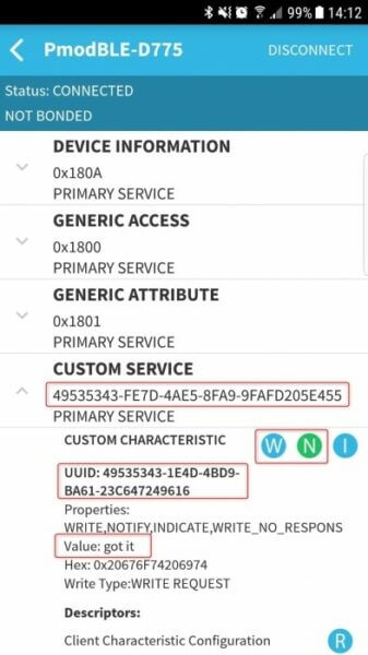
With the Pmods tested, the next stage is creating the Android app, followed by the LED driver and battery charging circuitry.
Designing the Android App
For the smartphone app, we use the MIT App Inventor. You will need a Google account to log in. If you don’t have one or if you would rather not use it for this exercise, you can access it anonymously from this page. Make a note of the re-enter code displayed, so you can continue your work at a later stage.
The first step is to create the user interface. You can do that from scratch, but you can also download our pre-built project file and import it. If you want to avoid bothering with the creation of the app at all, you can also download and install the final application. As a shortcut, scan the QR code below with your phone.
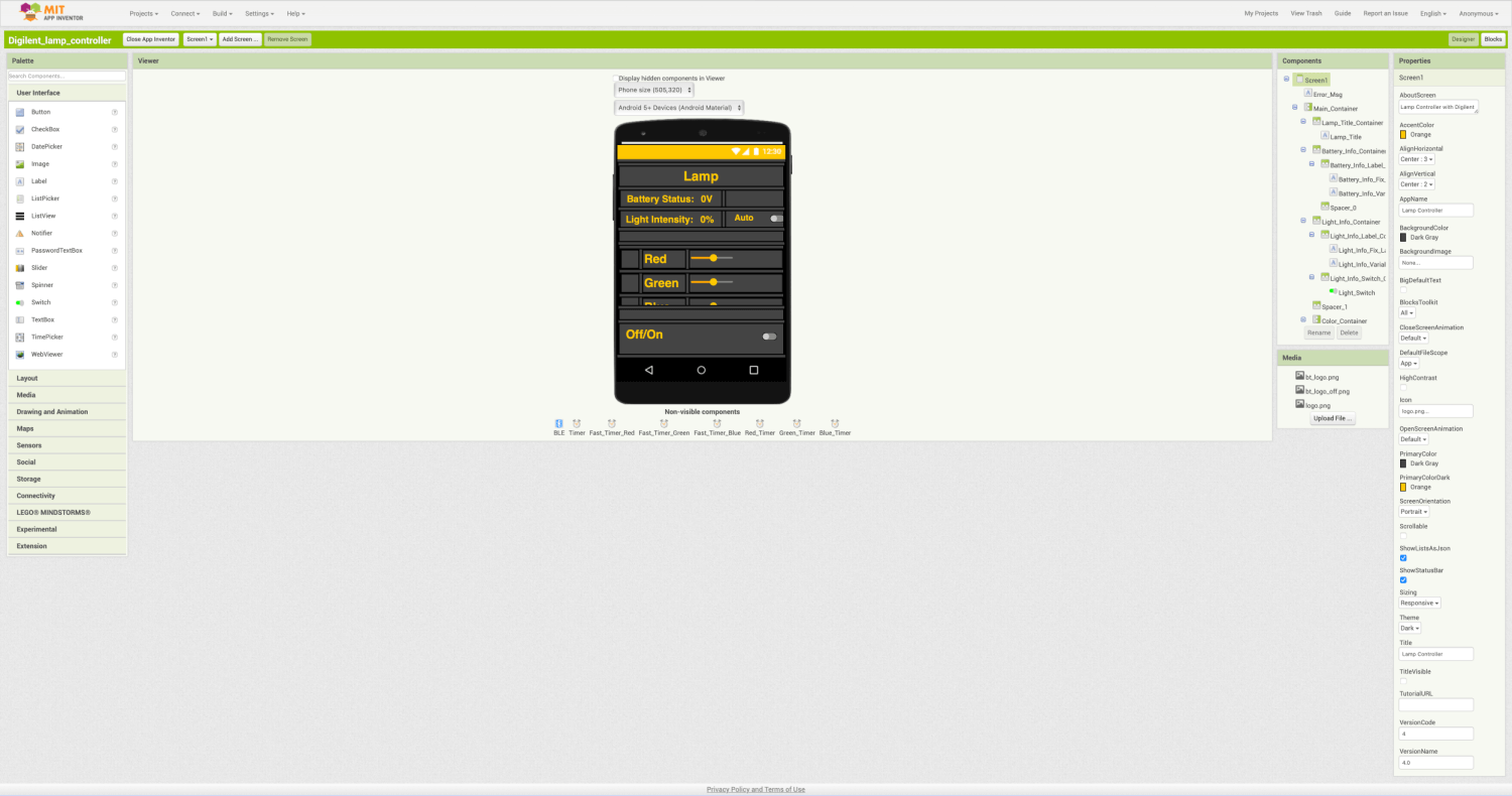
Our application needs two switches for turning the lamp on and off, and setting the intensity to auto. It also requires three sliders for the three colors red, green, and blue. Done with that, go to the Extension menu on the left and place the Bluetooth LE component on the screen of your virtual phone.
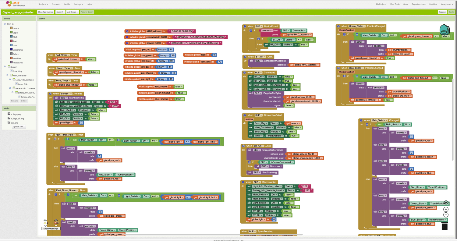
Now enter the Blocks view and create the logic behind your user interface elements and the non-visible components. Here, you define what happens once you interact with the screen and the different parts on it, like sliders, buttons, or labels. Also, think about what actions should take place when Bluetooth connects or disconnects, receives a message, or sends a message to the Pmod BLE.
Give a thought to the format you want to send the data in. Also review the data formats of the Pmods and how you intend to interpret them.
If asked for the MAC address for the Pmod BLE, the service UUID, and the Characteristic UUID, refer to your notes from the section above. There, you jotted them down.
If you believe you are all set, build the application and install it on your phone. Remember that it must allow installations from unknown sources.
Designing the LED Driver Circuit
Now it is time to design and assemble the LED driver. Here, to achieve linear brightness changes, you will need to control the current through the LED; just controlling the voltage is not sufficient. The ADP3450 does not feature a current supply, so you will have to design a voltage-controlled current sink for each of the LED’s colors.
The various voltages are created through PWM signals on the digital lines of the ADP3450, which you should connect to a low-pass filter. Have a look at the schematic below. Calculate the power dissipation and choose an adequate resistor. Finally, attach everything to the battery as shown.
Building the Charger Circuit
As a last step, create the charger circuit for the lithium-polymer battery cell. Use an LT 3092 programmable current source from Analog Devices for that and connect it with a USB-A plug to one of the USB ports at the back of the ADP3450. These provide enough power for charging the battery. Refer to the schematic below for details.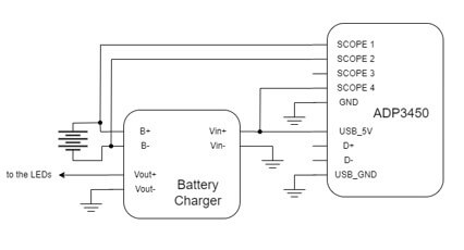
Now we are going to create the main script containing the application running on the Analog Discovery Pro ADP3450 from Digilent, working in Linux Mode. Once everything is complete, you will be able to adjust the luminosity and color of the LED through your phone’s app.
Bringing the Software Together
As before, you can either write the application from scratch following the guidelines below, or you can download it from here.
First, import all the modules you created during the previous parts of this blog series. Then define the constants needed and develop some helper functions, like one for decoding the incoming Bluetooth data. These functions make your life easier later on.
Once done, write the body of your program. For our solution, we used a try-except structure, but how you implement it is really up to you. Start with the initialization of the WaveForms instruments and the Pmods. Then move on and create an endless loop through a “while True” statement. Inside the loop, look for data packets received by the Pmod BLE and decode them. Query the ambient light brightness measured by the Pmod ALS as well. Eventually, you might want to read the voltage level of the battery and transmit it via Bluetooth to your smartphone.
At the end, you will need to provide code that allows you to exit your program gracefully. Define an event you want to react to, e.g., pressing “Ctrl+C”, and include statements that turn off the lamp and close and reset the WaveForms instruments.
Putting the ADP3450 in Linux Mode
Before you can run your script, you will need to put the Analog Discovery Pro ADP3450 in Linux Mode. For this, follow the steps detailed in the guide “Getting Started in Linux Mode with the Analog Discovery Pro (ADP3450/ADP3250)”. When finished, follow the instructions in the guide “Connecting the Analog Discovery Pro (ADP3450/ADP3250) to the Internet”. This will allow you to install the Python package installer (pip) directly on the mixed signal oscilloscope (MSO) using the command below:
sudo apt install python3-pip
Next, copy the HAL files you created for the WaveForms instruments earlier to your directory on the ADP3450. Before you can run the script, you have to execute the commands below from your terminal:
sudo su
cd /etc/systemd/system
echo -n “” > lamp.service
nano lamp.service
Now type the following text in your editor, but change the path according to your setup. Then save the file.
[Unit]
Description=Smart Lamp Controller
[Service]
ExecStart=nohup python3 /home/digilent/Smart-Lamp-Controller/Python/Lamp_Controller.py &
[Install]
WantedBy=multi-user.target
And finally, enable the new service and reboot the MSO:
systemctl start lamp
systemctl enable lamp
reboot
Running the Script
Once the ADP3450 has booted, start the script as well as the app you created on your smartphone. Wait until the phone detects the Pmod BLE, connect to it, and start playing with your sliders and switches in your app.
If you want to make any changes to your script, you will need to stop it by pressing your key combination, make your changes, and restart it. Enjoy your smart lamp!
A more detailed description of this project is available here (Digilent’s reference guide: “Building a Battery-Powered Smart Lamp with the Analog Discovery Pro”).


One Comment on “Build a Smart Lamp Using an Analog Discovery Pro ADP3450”