

This is the second installment of a series of four blog posts explaining how to design a smart RGB-lamp. If you are interested, you can find Part 1 here. By running an app on your smartphone, you can set the brightness and the color of the LED, or turn it off. The core of the system is an Analog Discovery Pro ADP3450, working in Linux Mode. It receives the settings from the smartphone’s app through a Pmod BLE, as well as the intensity of the ambient light, which is measured by a Pmod ALS light sensor.
In the previous post, we developed the hardware abstraction layer (HAL) functions for the Waveforms SDK. Now we design the software modules for the Pmods. We will do this similarly as before, but this time the code we create will two Pmods we use for our project and not ADP3450.
The Pmod BLE uses an UART for communication, and as we want to avoid an interruption of the PWM connected to the LED, we are going to implement it in two ways: the first one uses the UART instrument of Waveforms for sending and receiving data, the other one employs the logic analyzer and the pattern generator.
SPI is used to receive data from the Pmod ALS, and we use the Protocol Analyzer in WaveForms for that. As we will also need some I/O functionality, the Static I/O instrument is helpful.
Of course, you could write all the functions yourself, but it might be easier to download the module for the Pmod BLE from here and the one for the Pmod ALS from here. These Python scripts contain all the routines for our project, like open(), read(), or close() routines. It is worth noting that not all the functionality in these programs were tested, so there might be errors. Use them on your own responsibility.
Making Sure the Pmods Work
Before we can test the functionality of our Pmod, we need to connect them to the digital lines of the ADP3450. First connect the Pmod ALS. Have a look at the test-code to the right: it lists pin assignments. Link the CS-pin of the Pmod to the digital line 8 of the ADP 3450, the SDO pin to line 9, and the SCK pin to line 10. Moreover, connect VCC to VIO and the ground lines.
Finally, copy the code to a file in your working directory. Run the script and point a flashlight to the sensor on the Pmod. The intensity level should change.
To test the Pmod ALS, the ambient light intensity is read and displayed continuously.
# import modules
import Pmod_ALS as als
import WF_SDK as wf # import WaveForms instruments
from time import sleep
# define pins
als.pins.cs = 8
als.pins.sdo = 9
als.pins.sck = 10
try:
# initialize the interface
device_data = wf.device.open()
# check for connection errors
wf.device.check_error(device_data)
als.open()
while True:
# display measurements
light = als.read_percent(rx_mode=”static”, reopen=True)
print(“static: ” + str(light) + “%”)
light = als.read_percent(rx_mode=”spi”, reopen=True)
print(“spi: ” + str(light) + “%”)
sleep(0.5)
except KeyboardInterrupt:
pass
finally:
# close the device
als.close(reset=True)
wf.device.close(device_data)
Repeat the same exercise for the Pmod BLE. Again, the test script lists the connections. Copy the file to your hard drive as well and run it. To test the Pmod BLE, all messages received on Bluetooth are displayed, the string “ok” is sent as a response.
# import modules
import Pmod_BLE as ble
import WF_SDK as wf # import WaveForms instruments
# define pins
ble.pins.tx = 4
ble.pins.rx = 3
ble.pins.rst = 5
ble.pins.status = 6
# turn on messages
ble.settings.DEBUG = True
try:
# initialize the interface
device_data = wf.device.open()
# check for connection errors
wf.device.check_error(device_data)
ble.open()
ble.reset(rx_mode=”uart”, tx_mode=”uart”, reopen=True)
ble.reboot()
while True:
# check connection status
if ble.get_status():
# receive data
data, sys_msg, error = ble.read(blocking=True, rx_mode=”logic”, reopen=False)
# display data and system messages
if data != “”:
print(“data: ” + data) # display it
ble.write_data(“ok”, tx_mode=”pattern”, reopen=False) # and send response
elif sys_msg != “”:
print(“system: ” + sys_msg)
elif error != “”:
print(“error: ” + error) # display the error
except KeyboardInterrupt:
pass
finally:
# close the device
ble.close(reset=True)
wf.device.close(device_data)
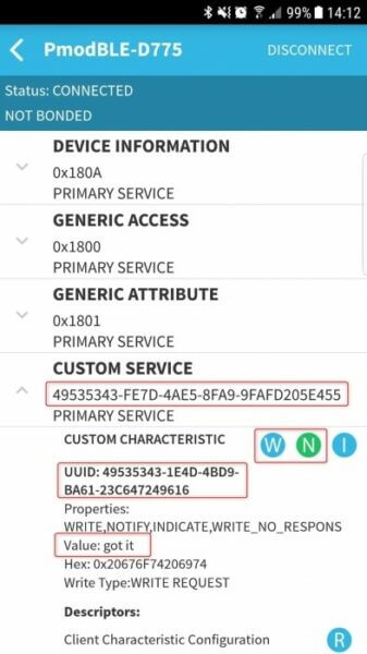
In addition, download the BLE Scanner application to your phone and start it. Turn on Bluetooth, if it is not already running, as well as the location. The app should display the Pmod BLE after some time. Connect to it and jot down the long code (MAC address) below the device’s name. You will need it later.

Open the Custom Service dialog and hit the “N“ (notify) icon and some system messages should show in the terminal of the test script. The “Got it“ string should appear on the custom characteristic screen of the app. Now tap “W“ and type in your text. Write down the value for the UUID and the characteristic. As before, you will need them later.
This concludes the second installment of this blog-post series. In the next edition, we will create the controlling Android app and the LED and charger circuits.
One Comment on “Build a Smart Lamp Using an Analog Discovery Pro ADP3450 – Part 2”