

A logic analyzer can be thought of as the oscilloscope for digital signals. An oscilloscope for an analog signal is important because the waveform is technically changing at every infinitesimal point along its curve; think of a sine or cosine wave. Since digital signals are all about high/low logic, duty cycle, and frequency which are all just ways to describe how a square wave is changing, the use of an oscilloscope would be overkill for “looking” at the signal. Instead, most digital signals are typically running along with other digital signals that interact with each other in specific and important ways. A logic analyzer specializes in observing and measuring these relationships between digital signals while focusing on the parts of the signal that are important, which is usually not so much the shape since the digital signal will typically be in some form of a square wave. Below is an illustrative comparison of analog signal and digital square wave signal to show how an oscilloscope view of a digital signal is not as exciting or meaningful. We have to use images that are publicly available for commercial use and this photo seemed to illustrate my point the best out of what was available. Bonus points if you comment with the translation. Photo from here.
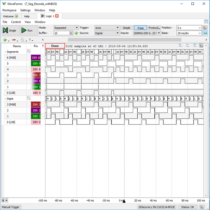
A great example of when to use a logic analyzer is while debugging a digital bus signal where the bit value of that bus is of concern. Another example is debugging protocols like I2C, SPI, UART, or CAN. These operations involve multiple digital signals, sometimes many, and how they interact with each other is key to their performance. If you looked at this on an oscilloscope you would be able to see the shape of the square waves, which would tell you if the signal is active, but not if the data being transmitted is correct. Logic analyzers typically provide the ability to decode protocols, that is, take the square waves and display the actual transmitted data. Usually, there are multiple square waves and the combination of those square waves are what make up and give meaning to the transmitted data. Below is an example of a seven segment display debug in the WaveForms logic analyzer (using the Digital Discovery). Take a look at the bottom four signal lines and note that the logic analyzer groups them into a bus above those lines and displays what the decimal numeric value of that bus is with each change in logic signal. Right click the image to view a larger version.
As you might be seeing now, an oscilloscope would not help with this kind of analysis as digital busses can get complicated quickly, and the relationships between each square wave are essentially more important than seeing one or two individual square waves over time. Also, like an analog oscilloscope, a logic analyzer utilizes a trigger to optimize a stable display of dynamic signals and data acquisition. Check out my post on triggers for more info on that.
And remember, if your looking for some hardware to get started with a logic analyzer (or electronics in general) make sure to sign up for our Cyber Week deals- starting today! Simply sign up and you will receive an email a day until November 30th with a coupon code for deals on some of our most popular products, including the Analog Discovery 2, Embedded Vision Kit, Pmods, Arty, Cora and the OpenScope MZ.
So do not miss out, and sign up today!