UART is an acronym for Universal Asynchronous Receiver-Transmitter. Sounds spiffy, right? This is an example of electronics communication protocol: how systems and devices can transmit and receive data from one another.

Please hold while I connect your devices. Photo from here.
Turns out, UART is a physical section of circuitry involving a large scale integrated circuit, that is in essence a translator between parallel and serial data lines. There are “stand-alone” UART chips, but these days they are more commonly found within a microcontroller. The UART communicates with the rest of the microcontroller or computer system by the parallel data bus, and converts it to a serial data stream so that it can be transferred over one single wire (or possibly IR or Bluetooth signal) to another UART device. Parallel data transfer is much faster than serial, but more expensive in terms of hardware and power consumption, so a serial data line between devices is usually a desirable compromise in situations such as embedded systems. Some UARTs have buffers to help coordination between the parallel and serial data lines for received data.
In a basic approach, a UART is a 2-wire system: TX (transmission of data) and RX (receiving of data). However, power and ground wires are usually required as well. This is a bit (pun intended) different than some other protocols as there is no clock signal that is transmitted between receivers. This is nice because it saves data space. However, there are internal clocks in both the transmitter and receiver and these internal clock frequencies need to be specified ahead of time and agree with each other for proper communication and synchronization.
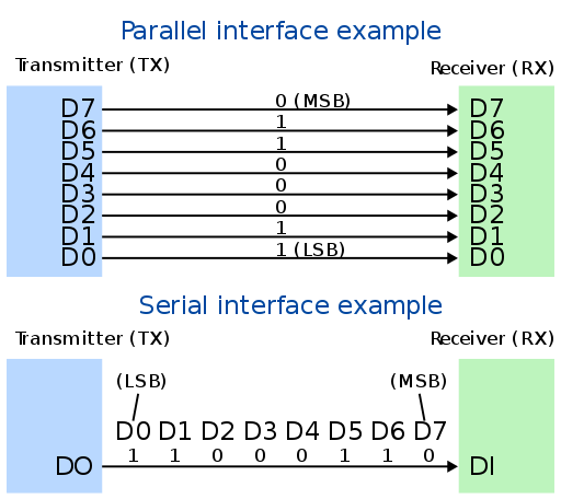
Below is an example that illustrates the difference of parallel and serial data lines. Note that only one wire is shown in the serial interface but another would be needed for RX to send data to TX. Photo from here.
Instead of using a transmitted clock signal with data collection, UART uses what are called Start Bits and Stop Bits to signify the beginning and end of a bit-wise data packet. These bits do not carry any of the transmitting/receiving data. The signal lines typically idle at a logic high level, so the Start Bit is typically a logic low level and the Stop bit is typically the logic high level. When the receiver detects the drop in voltage, it knows to start collecting data. At the end of the data stream, the signal is driven back to a high logic level to indicate the end of the data packet.
There is also what is called a Parity Bit that is added to the data packet before transmission. There are two types of parity bits: an Odd Parity Bit and an Even Parity Bit. An Odd Parity Bit will be at a logic level high if there are an even amount of logic high bits in the data transmission to force an odd amount of high level logic bits between the Start Bit and the Stop Bit. Conversely, an Even Parity Bit will be at a logic level high if there are an odd amount of logic level high bits in the data transmission forcing an even amount of logic level high bits between the Start Bit and Stop Bit. This is a loose form of error protection as the receiver UART will be expecting either an odd or even amount of logic level high bits in the data transmission for every data packet. Depending on the circumstances, data bits can become corrupt during transmission and change state. For example: if using an Even Parity Bit system, the number of logic level high values is odd, and the Even Parity Bit is high, then an error is detected and the data is determined to be corrupt. Unfortunately, the UART will only make that determination and can not find which bit(s) became corrupt.
Another important parameter for UART is called the Baud Rate. This is the rate in which data bits can be transmitted/received in units of bits per second. One common Baud Rate is 9600 bits per second, which corresponds to 1/9600 seconds per bit. The Baud Rate of two communicating UARTs must be within 10% of each other.
The diagram below shows the idea of the entire data packet (also called frame). Image from here.

The last stop in our survey of UART is to touch on how the receiver samples the data from the transmitter, since they do not share a common clock signal. The receiver and the transmitter will be operating at the same internal clock frequencies, but their switching state between logic level high and low are almost guaranteed to be out of phase. This means that the transmitter’s falling edge of the Start Bit can happen at any time during the receiver’s clock cycle. Because of this, the receiver over samples the transmission by some factor of the Baud Rate to approximate where the midpoint of the bit period is. Sampling near the midpoint helps prevent sampling near rising/falling edges when clock cycles are more or less out of phase. For example: let’s consider a receiver that is sampling at 16 times the Baud Rate of transmission. When the Start Bit is detected, the receiver will wait 8 clock cycles to approximate the midpoint of the Start Bit. Then, the receiver will wait 16 clock cycles from then to start data acquisition, as it will be near the midpoint of the first data bit. Note that the higher the sampling rate, the closer the approximation of the bit’s midpoint at the cost of higher power consumption.
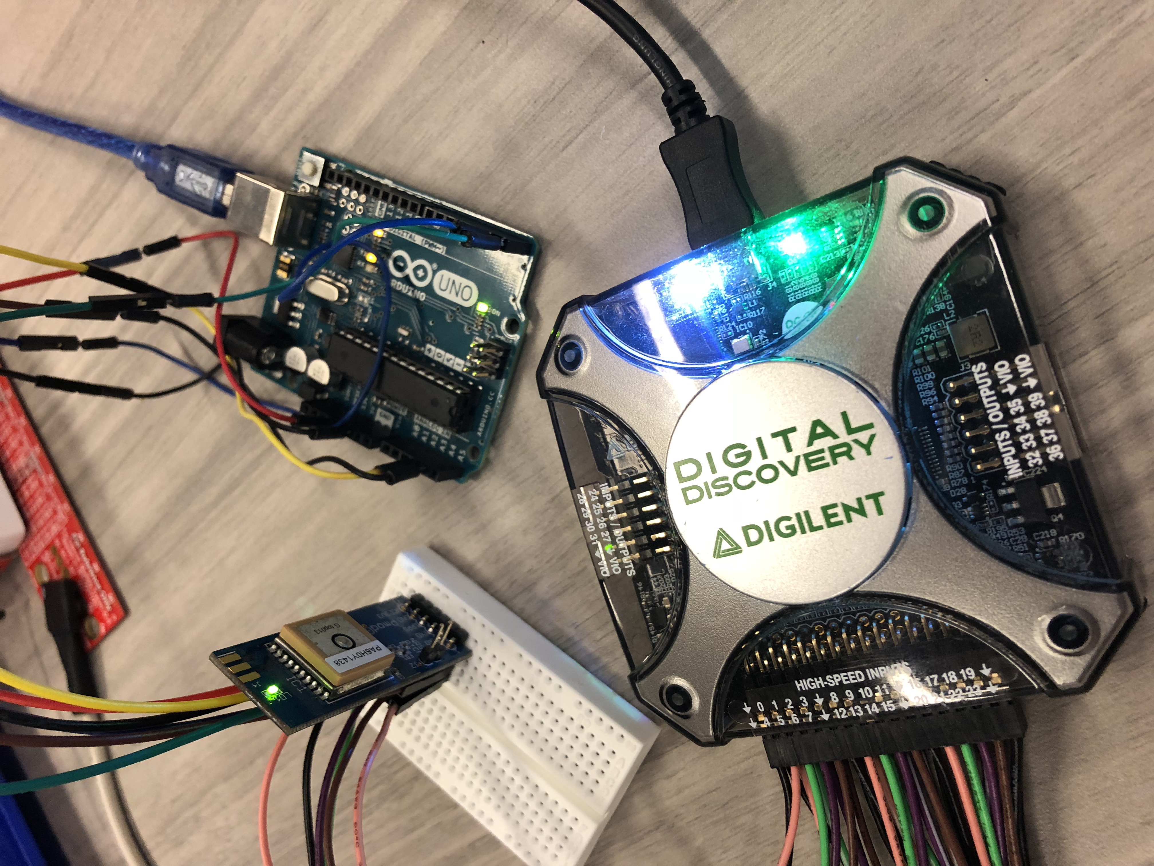
Now, let’s take a look at some UART signals using the Digital Discovery and WaveForms Logic Analyzer (you can also use the AD2). I am working on a project for a sensor systems class and my group wanted to use the PmodGPS to work with GPS data. Using an Arduino Uno and the Digilent provided library for the PmodGPS, I was able to program the microcontroller to display GPS data on the serial monitor (setup pictured above). However, as the print statement on the serial monitor was telling me, the GPS sensor was not connecting to any satellites. To make sure the sensor was operating correctly, I used the Digital Discovery’s Logic Analyzer to see what was happening on each pin and make sure it’s at least functioning correctly and is not connecting due to being inside a giant brick building in downtown Seattle or UW Bothell.
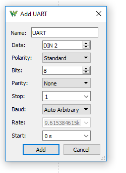
Below is a screen shot from the Logic Analyzer window and selecting the parameters for the UART bus. There is a bus of all the pins except ground and a separate UART bus. Right-click the image(s) and open in a new tab to see a larger view.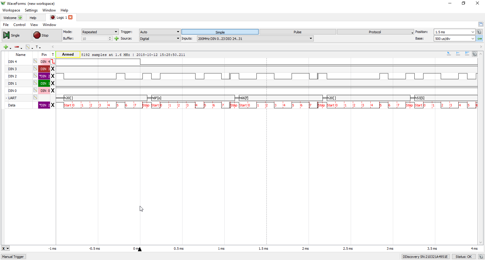
The pin connections are as follows: DIN4 is 3DF, DIN3 is RX, DIN2 is TX, DIN1 is 1PPS, and DIN0 is VCC. VCC is continuously logic level high as expected, RX is continuously logic level high because the Arduino is not sending data to the PmodGPS, and TX is in fact sending data. The 3DF pin indicates the status of the user’s positional fix. When the module has a constant fix (2D or 3D) this pin stays low, if the module is unable to get a fix then the pin will toggle every second. I adjusted the time scale axis and saw that the latter was the case: the 3DF was toggling every second. Further, the 1PPS pin provides a one pulse per-second output synchronized with GPS time. Since the 3DF pin was toggling every second and the 1PPS pin was not toggling at all, I knew that the PmodGPS sensor was operating but not getting satellite signals in its current location. Below is a screen shot from the Logic Analyzer window in WaveForms with time scaled outward to see the 3DF toggle. Right-click the image and open in a new tab to see a larger view.
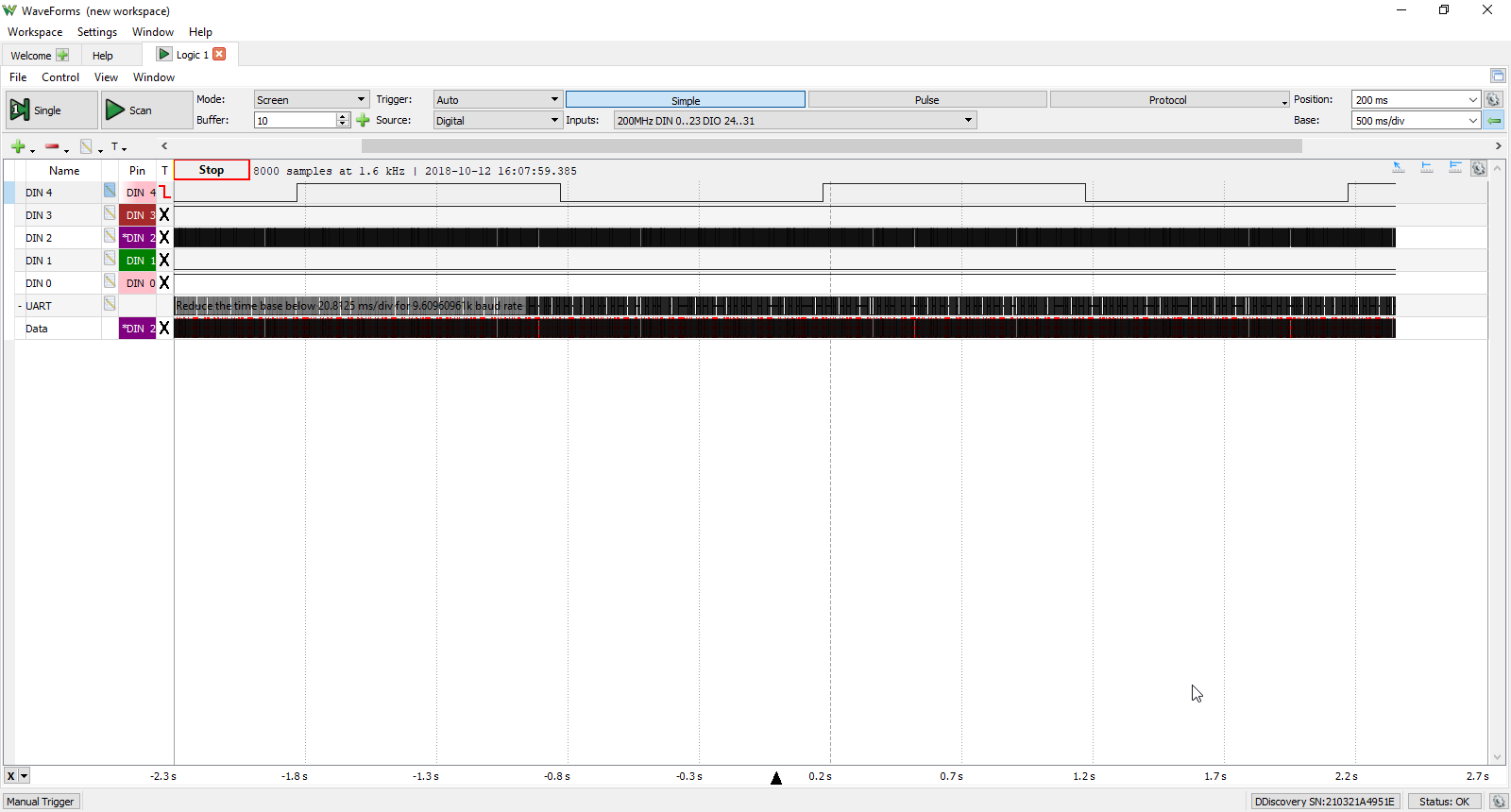
The Digital Discovery and the Logic Analyzer in WaveForms helped lay to rest the question of whether the PmodGPS sensor was operating at all. I hope this was as informative for you as it was for me; now I have to go figure out how to get the attention of satellites. Thanks for reading!


Helpful information…thanks for sharing such a good piece of info.
I am glad you found this post helpful! Thanks for reading!
Great article! Java has earned its status as one of the main programming dialects for big business applications.
Very helpful..
Very Useful Content. Thanks for sharing with us.
Great read on UART! As someone deeply involved in IT training at Analytiq Learning, I found this blog post to be an excellent resource for both beginners and advanced learners. The clear explanation of UART (Universal Asynchronous Receiver/Transmitter) and its applications in communication protocols is incredibly insightful. At Analytiq Learning, we emphasize the importance of understanding such foundational concepts, as they are crucial for anyone looking to excel in embedded systems, IoT, or hardware interfacing. This post aligns perfectly with our mission to provide cutting-edge knowledge and practical skills to our students. Looking forward to more such informative content! Keep up the great work!
#EmbeddedSystems #IoT #ITTraining #AnalytiqLearning #UART #TechEducation