

Today we will pick up where we left off from our last post, continuing our discussion on the effects of how ground potential differences can impact oscilloscope measurements. From the end of part one:
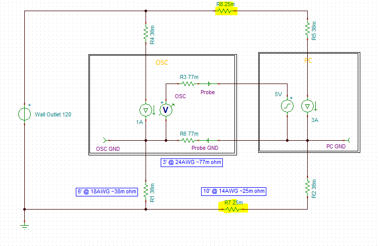
What is happening, the oscilloscope and the PC have different internal ground potentials because of the IR drop in their respective power cords. We can see there is a 38.25mV different (our 0.5a * 77mΩ = ~38mV)
But again, this isn’t reality. In reality, there is some resistance in the wall branch circuit between the PC and the oscilloscope. Now a 15 amp wall branch circuit will typically use 14 AWG wire. Let’s assume that our PC is upwind of our oscilloscope by 10 feet between 2 wall outlets. Given our chart, that would yield a wall resistance of about 25mΩ (10*2.525/1000 = ~25mΩ).
To continue, let’s update our schematic to include the 25mΩ wall resistance between our instruments.
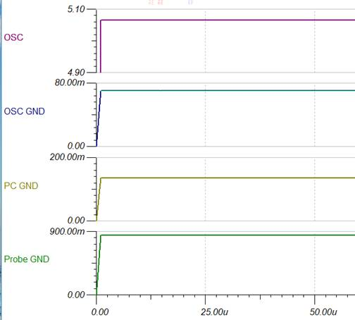
We now measure 5.07v on the oscilloscope, a 70mV offset error. Our 24 AWG Probe ground wire is passing 848mA, and the difference between the PC and oscilloscope internal grounds is now 65mV.
But this still really isn’t reality. In reality, there is probably something else plugged into our wall branch circuit besides just the PC and oscilloscope. Our wall circuit can provide 15 amps from the branch circuit breaker. Our PC takes 3A, or oscilloscope takes 1A, let’s add something big upstream on the branch circuit, say a 7A appliance.
Let’s add that to our circuit.
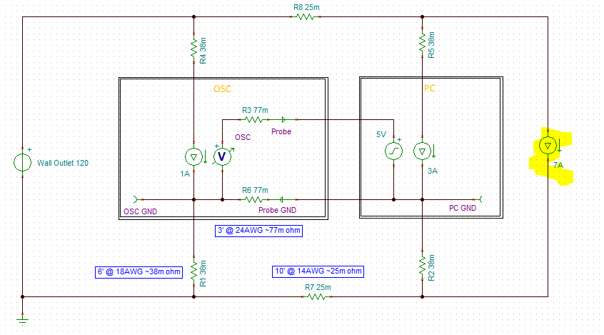
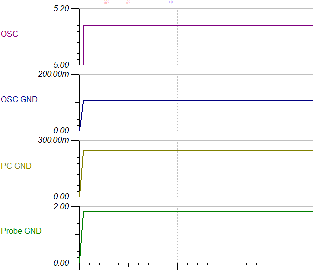
Now we measure 5.14mV on our oscilloscope, an offset error of 140mV! Our 24 AWG probe ground wire is passing 1.83 amps! That probe ground wire might be getting warm!
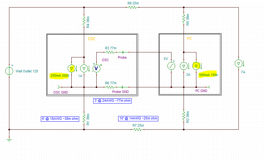
But this really isn’t reality. In reality there is probably some switching noise going on in the PC and oscilloscope. Let’s simulate that with a 500mA 100kHz square wave on the PC, and 250mA 500kHz triangle wave on the oscilloscope.
Let’s add that to our circuit.
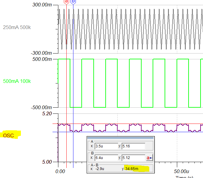
We see a 34.6mV ripple on our oscilloscope measurement!
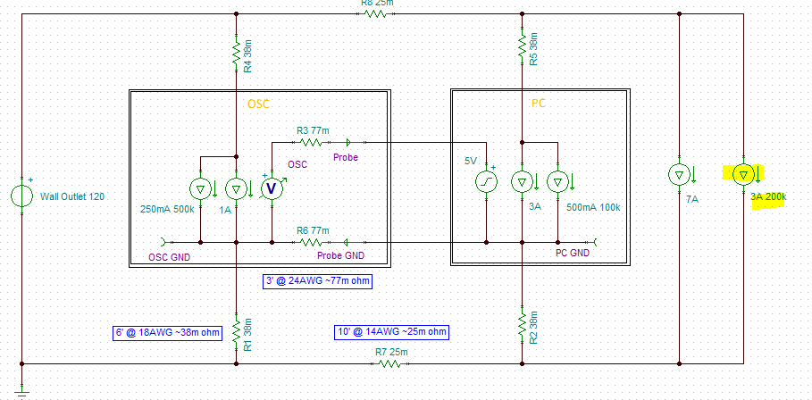
But let’s not stop just yet! Let’s add upstream on our wall branch circuit a noisy appliance. Now typically it would probably be at 60Hz, but that is going to be hard to show, so we am going to put a 3A 200kHz sine wave appliance on the circuit. We picked 200kHz so we can easily see the effects on our simulated oscilloscope trace. In reality, it probably would be a much lower frequency appliance, but the effect would still be there.
For fun, let’s add that to our wall branch circuit.
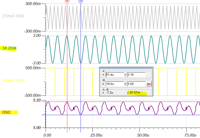
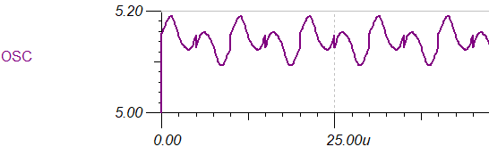
Now we have nearly 100mV of ripple measured on the oscilloscope and a really ugly looking waveform!
So here we are, using our nice expensive Tektronix’s oscilloscope, attempting to measure a nice steady 5v source from our PC; and what do we see? We see a messy signal offset by 140mV!
Our nice 5v output doesn’t look so nice anymore, but it really isn’t real, it is a scope measurement distortion due to differentiating ground references.
Now let’s take a look at what we have on my desk; a real world condition. Let’s measure my PC USB ground against our Tektronix’s ground (ground to ground) with my Agilent DMM (which has an isolated ground). We see a 95mV of ground differential between the PC and the Tek. This is due to the IR drop in the power cords and in the wiring in the wall, the branch circuit.

But, beware; even though this shows 95mV of difference, as soon as I hook up the probe ground wire, the grounds will equalize via the probe’s ground wire and the difference will be greatly reduced. But, there will be an IR drop across the probe ground wire and that is what will show up as an offset error on the scope trace. For example, when we hook up the probe ground to my PC, my offset error drops to 5.5mV; and in reality, we typically see anywhere from 5-15mV of offset error on my Tek.
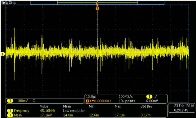
Using a differential probe (ground to ground), we can see hundreds of mVs of noise (probably switching noise). This will all show up as additional noise on any scope trace.
So how do we fix this? How do we see what is really there?
- Ideally, if we could get the scope and the unit under test to have the same ground potential, and without switching noise, our single ended scope would work just fine.
- One thing we can do is couple the grounds of the scope and the unit under test with a very heavy gauge wire; reducing, but not illuminating, the ground differences.
- Use a scope with an isolated ground.
- This will allow the scope to float to the same ground potential as the unit under test.
- There will still be some capacitive coupling that can allow interference to affect the signal measurement, but usually this is minimal.
- The OpenScope and OpenLogger can have isolated grounds by powering them off of a battery and using WiFi to talk to them. This completely isolates the scope from any external interference.
- This will allow the scope to float to the same ground potential as the unit under test.
- Use a differential probe
- This allows one probe to trace the unit under test’s ground, while the other probe measures the signal relative to that ground.
- But differential probes are expensive. If I need one, I have to borrow it.
- Use averaging on the scope to remove noise, and know what the nominal offset error is.
- This is what I do most of the time.
- Sometimes, you just don’t know what is real, and what is interference. Judgement and discussions with others are the best that can be done.
I’m surprised at the claim “But differential probes are expensive. If I need one, I have to borrow it.” Don’t Digilent employees get Analog Discovery 2 scopes with built-in differential inputs?
Thanks Miranda. This is a really good and important article. What you see is not necessarily reality!
I have been using an Analog Discovery 2 on a daily basis for about a year now, and have been battling with ground loop induced noise for a while. I suspected it, but had never proven it until reading this and then making some strategic measurements to prove that is what I was seeing. So very useful.
Most of my work with the scope was prototyping on breadboard proving designs for subsystems. I was powering the breadboard with one of those these
https://www.amazon.co.uk/Breadboard-Power-Supply-Module-Solderless/dp/B00BXWV2F6
It had a cheap wall mounted SMPS plugged into it supply 7.5V. The above unit has an LDO on it, regulating that down to 5V/3.3V. The Analog discovery 2 was plugged into a passive USB Hub connected to my desktop PC. So, lots of potential for ground potential induced noise…. In my case that manifested itself as somewhat irregular spikes about 100mV peak-to-peak at about 3kHz. Pretty ugly. For a long time I blamed it on the SMPS and the poor LDO on that breadboard.
Yesterday, in order to try to improve the situation, I tried a different config. I turned the wall mounted SMPS down to 5V and plugged it into the AD2 auxiliary power supply input. Then I used the AD2 configurable supplies to power the circuit under test on the breadboard. ie the GND for the circuit is coming directly from (!) the AD2.
Huge difference! the 100mV 3Khz spikes disappeared into the noise floor. There are some much smaller ones at about 15mV @ a much higher frequency of ~30kHz. This is coming from that SMPS.
But the situation is much improved.
Thanks, just wanted to note here in case it helps someone.