

What is SPI? That is a question I asked myself a couple of months ago that I am glad to answer now! After an introduction to SPI protocol, I will show an example of SPI protocol signals using the Analog Discovery 2, WaveForms, and a PmodALS.
SPI is an acronym for Serial Peripheral Interface. Okay, so what is that? It is one form of electronics communication protocol: how something like a microcontroller (or some “master” device) can send/receive data from external electronics such as sensors, shift registers, and SD cards (called “slave” devices) over a short distance.
A serial communication sends one bit of data at a time over one wire, whereas a parallel communication sends all bits of data at once on individual wires. SPI also sends data in a continuous stream, which means that the transfer itself does not interrupt the acquisition. This is awesome because the data will be of higher quality than if sampling had to be interrupted for acquisition.

Your data: the continuous stream. Photo from here.
SPI is a 4-wire Bus system: Master-In-Slave-Out (MISO, SDO on some slave devices), Master-Out-Slave-In (MOSI), Slave-Select/Chip Select (SS, SSN, or CS), and Serial-Clock (SCLK or CLK). However, power and ground wires are usually present as well.
The MOSI line transmits data bits from the microcontroller to the peripheral device, the MISO transmits data bits from the peripheral device to the microcontroller, the SS/CS is controlled by the master device and is used to select the peripheral device for data transfer (“start/stop” if connected to only one peripheral or to select between multiple peripherals). Multiple slave devices can be connected, but each slave device will require its own SS/CS wire to the master device. For example, here is a system with one master and four slave devices.
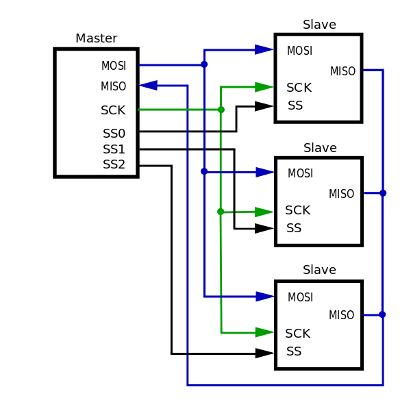
A SPI connection diagram with multiple slave devices. Photo from here.
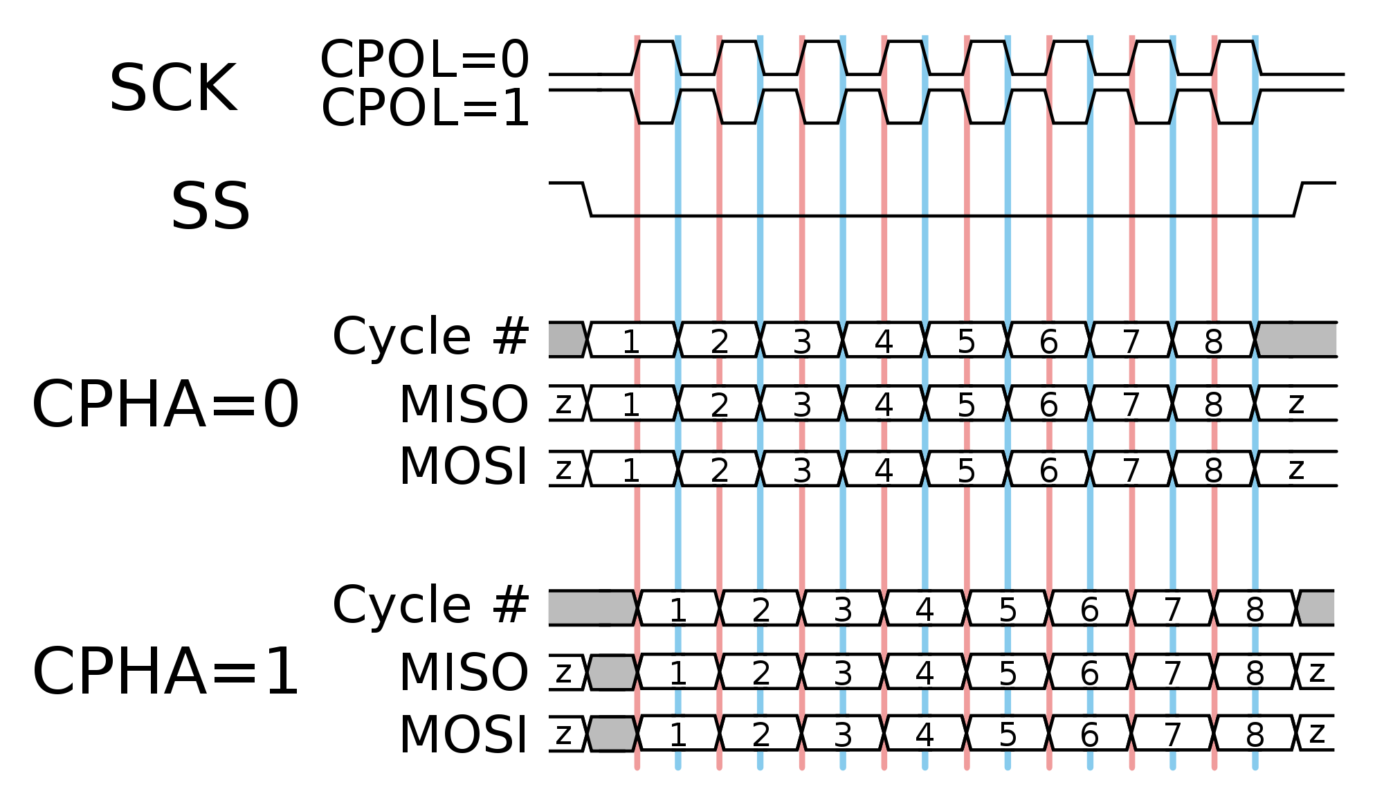
Be aware though that SPI has not been standardized and that depending on the system architecture, implementation of the data transmission may vary. There are four general modes of SPI communication that the master device must configure. This is to compliment the bus design of the slave device and is based on the Serial Clock Polarity (CPOL) and Phase (CPHA). Both parameters can be expressed as low and high or 0 and 1. CPOL defines whether the serial clock idles (when data transmission is not occurring) at a low or high level logic (0 or 1, respectively) and CPHA defines whether data is sampled on the leading or trailing edge (0 or 1, respectively) of the CPOL.
The diagram below shows what each signal would look like given the variations to each. Image from here.
Furthermore, transmission can begin with either the Least-Significant-Bit (LSB) or the Most-Significant-Bit (MSB). There is also a choice of sampling frequency, which is equally important and is a choice dependent on the limitations of the devices you are using and the frequency or resolution of the data you are trying to sample. Always check the datasheets for the system you are working with to verify defaults, modes of operation, and limitations.
Now, let’s take a look at an example of SPI protocol using the Analog Discovery 2 and WaveForms. I used the Pmod ALS (Ambient Light Sensor) as my slave device, an Arduino Uno as the master device, and the code from the hackster project here to display the SPI protocol.
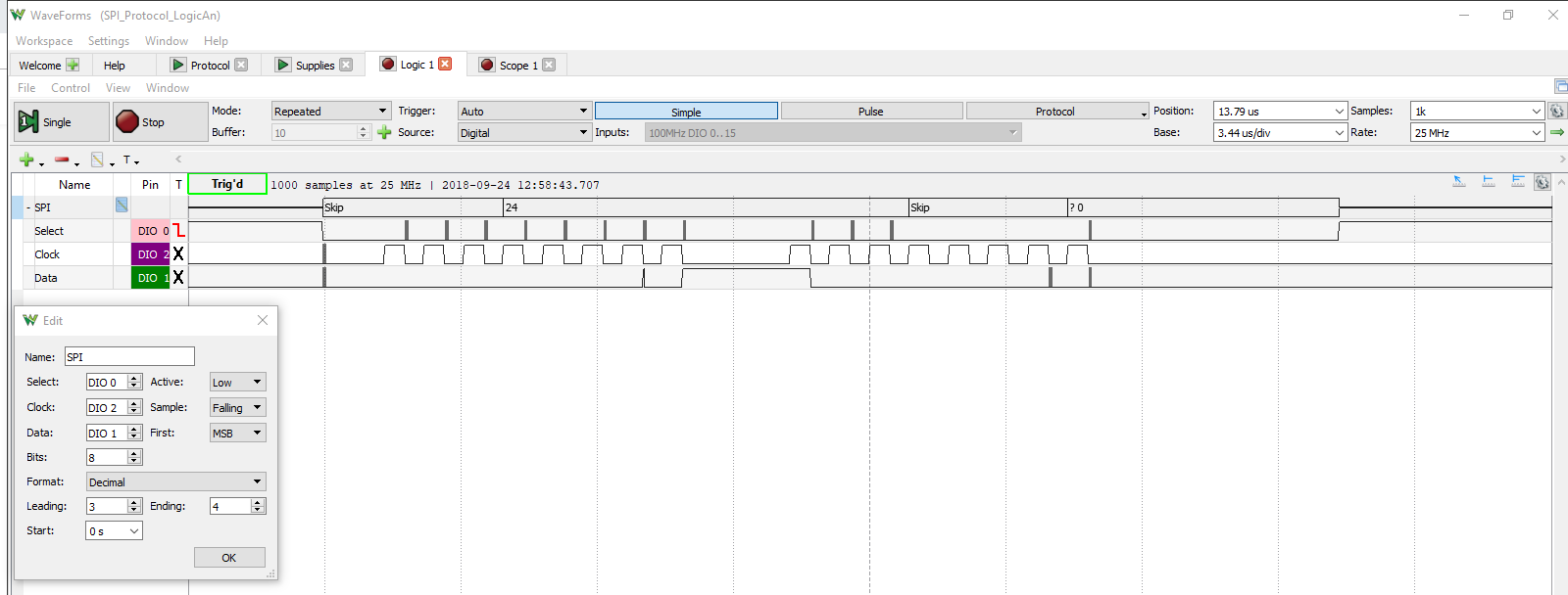
Right-click the picture and open in a new window/tab to see a larger version of this image. The Logic Analyzer in WaveForms is an especially handy tool when debugging SPI and other protocol. For example, when setting up this demo, I accidentally used a damaged PmodTPH. Through the use of the Logic Analyzer, I was able to determine that the TPH was damaged and not the Pmod ALS. Once I removed that Pmod and adjusted the trigger settings, I saw the signals operating correctly!
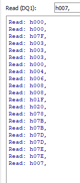
The Analog Discovery 2‘s Protocol Analyzer is another tool that can help determine if your slave device is sending data appropriately. Here is a screen shot of the Protocol Analyzer showing a dynamic output (in hexadecimal) as I change the amount of light that the PmodALS is experiencing (disregard the 7F value, that was from me touching and shorting the leads).
Now you know enough about SPI, and some valuable debugging tools, to be able to start experimenting and getting your hands into some SPI protocol projects. Happy trails!
One Comment on “What Is Serial Peripheral Interface (SPI)?”