

Last week we introduced the Pmod COLOR, our newest sensor Pmod. The Pmod COLOR is a color light sensor, as the name suggests, that communicates the intensity of red, blue, green (RGB) and clear (non-filtered) light present over a simple I2C bus. It is designed for use at close range and is great for object sorting, color temperature measurements and colorimetry applications.
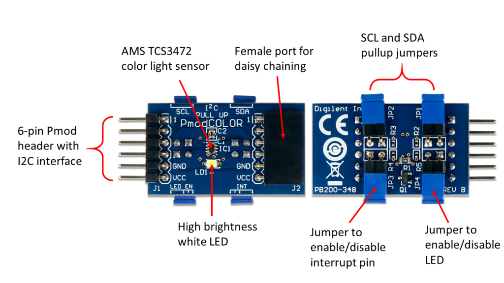
For more information on how the hardware works, you can read the previous post or visit the Pmod COLOR reference manual. Here we’ll focus on how to get it up and running in software.
Quick Start with the Pmod COLOR
Below you’ll find the set of commands necessary for acquiring data from the Pmod COLOR over its I2C bus.
-
Power on the Pmod COLOR.
-
Provide a START condition and call the device ID with a write bit
I2CBegin(0x52); //device ID 0x29 with a write (0) bit
-
Wait to receive an ACK from the Pmod COLOR.
-
Provide a command to maintain the pointer address OR’d with the Enable register (0x00)
I2CWrite(0xA0); //Maintain the pointer address at the Enable register
-
Wait to receive an ACK from the Pmod COLOR.
-
Send the Enable Address and enable the oscillators.
I2CWrite(0x01); //0x01 enables the oscillators for the timers and ADC channels
-
Delay at least 2.4 mS before starting a data collection initiation.
-
Send the Enable Address and enable the ADCs for all 4 channels.
I2CWrite(0x02); //0x02 enables the ADC channels
-
Wait to receive an ACK from the Pmod COLOR and then send a STOP condition.
-
Delay 2.4 ms for the ADCs preparing themselves for data measurement and at least 2.4 ms by default for the integration time during the data collection process.
-
Send a START condition and call the device ID with a write bit
I2CBegin(0x52); //device ID 0x29 with a write (0) bit
-
Wait to receive an ACK from the Pmod COLOR.
-
Provide a command to auto-increment the address pointer OR’d with the first data register (0x14)
I2CWrite(0xB4); //Auto-increment the pointer address starting at the Clear Data Low Byte register
-
Wait to receive an ACK from the Pmod COLOR
-
Provide a RESTART condition and call the device ID with a read bit
I2CBegin(0x53); //device ID 0x29 with a read (1) bit
-
Wait to receive an ACK from the Pmod COLOR.
-
Collect all 8 data bytes corresponding to the low and high data byte registers of the clear, red, green, and blue data, respectively, waiting to receive an ACK from the Pmod Color between each byte.
I2CReadMultiple(8); //read in the 8 data registers taking advantage of the auto-incrementing pointer
-
Send a STOP condition.
If you’d like to see a complete program that implements the above steps, go to the Pmod COLOR resource center. Here you’ll find an example Arduino program as well as links to our Pmod IP core tutorial for quick drag and drop use with Microblaze designs. In addition, one of our applications engineers created a demo on our new Digilent projects site, projects.blog.digilentinc.com, using the Pmod COLOR IP core and the Zybo board to display color reading using Python.
For any questions or comments, visit the Digilent Forum or post in the comments section below!