Pmod COLOR Reference Manual
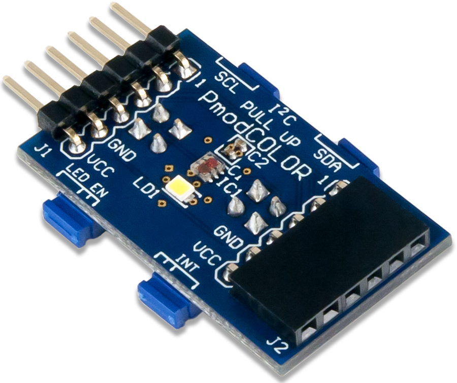
The Digilent Pmod COLOR (Revision A) is a color sensor module with the ability to sense red, green, blue and clear light. The onboard AMS TCS3472 integrates an IR blocking filter to accurately determine the color of objects as well as sense ambient light under varying lighting conditions and through attenuating materials.

Features
- Red, green, blue, and clear light sensing
- IR-blocking filter
- White LED for reflective measurements
- Suitable for use behind darkened glass
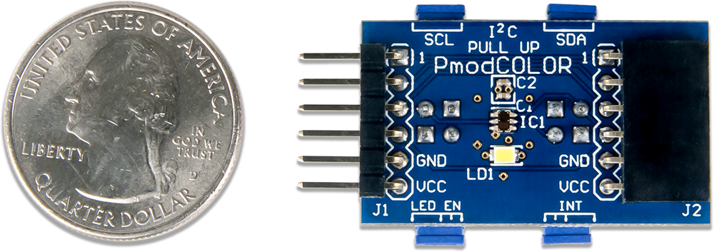
- Small PCB size for flexible designs 0.8“ × 1.25” (2.0 cm × 3.2 cm)
- 6-pin Pmod connector with I²C interface
- Pass-through Pmod host port for daisy chaining
- Follows Digilent Pmod Interface Specification Type 6
- Library and example code available on the Resource Center
Specifications
| Parameter | Min | Typical | Max | Units |
|---|---|---|---|---|
| Power Supply Voltage | 2.7 | 3 | 3.6 | V |
| Parameter | Channel | Min | Max | Units |
| Responsivity to blue light (λ = 465 nm) | Red Channel¹ | 0% | 15% | counts/μW/cm² |
| Green Channel¹ | 10% | 42% | counts/μW/cm² | |
| Blue Channel¹ | 65% | 88% | counts/μW/cm² | |
| Clear Channel | 11.0 | 16.6 | counts/μW/cm² | |
| Responsivity to green light (λ = 525 nm) | Red Channel¹ | 4% | 25% | counts/μW/cm² |
| Green Channel¹ | 60% | 85% | counts/μW/cm² | |
| Blue Channel¹ | 10% | 45% | counts/μW/cm² | |
| Clear Channel | 13.2 | 20.0 | counts/μW/cm² | |
| Responsivity to red light (λ = 615 nm) | Red Channel¹ | 80% | 110% | counts/μW/cm² |
| Green Channel¹ | 0% | 14% | counts/μW/cm² | |
| Blue Channel¹ | 5% | 24% | counts/μW/cm² | |
| Clear Channel | 15.6 | 23.4 | counts/μW/cm² | |
| Parameter | Value | Units | ||
| Output Resolution | 16 | bits | ||
¹ - Percent values are with respect to the counts measured by the clear (non-color filtered) channel
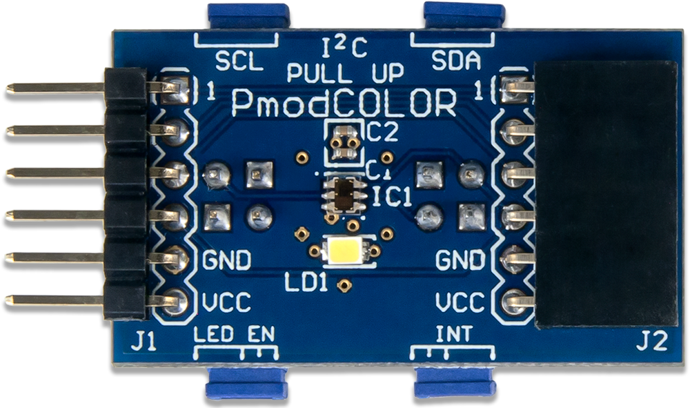
Pinout Table Diagram
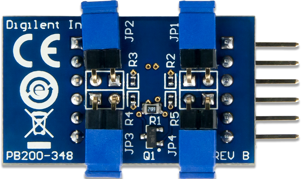
| Header J1 | Header J2 | Jumper JP1 | ||||||
|---|---|---|---|---|---|---|---|---|
| Pin | Signal | Description | Pin | Signal | Description | Pin | Status | Description |
| 1 | IO1/~INT | I/O pin 1 or active low interrupt | 1 | IO1/~INT | I/O pin 1 or active low interrupt | SCL | Loaded/ Unloaded | 2.2 kΩ Pullup to Vcc/No Pullup to Vcc |
| 2 | IO2/LED_EN | I/O pin 2 or LED enable | 2 | IO2/LED_EN | I/O pin 2 or LED enable | Jumper JP2 | ||
| 3 | SCL | Serial Clock | 3 | SCL | Serial Clock | SDA | Loaded/ Unloaded | 2.2 kΩ Pullup to Vcc/No Pullup to Vcc |
| 4 | SDA | Serial Data | 4 | SDA | Serial Data | Jumper JP3 | ||
| 5 | GND | Power Supply Ground | 5 | GND | Power Supply Ground | ~INT | Loaded/ Unloaded | Enable/Disable the active low interrupt |
| 6 | VCC | Power Supply (3.3V) | 6 | VCC | Power Supply (3.3V) | Jumper JP4 | ||
| LED_EN | Loaded/ Unloaded | Enable/Disable the LED enable pin | ||||||
Physical Dimensions
The pins on the pin header are spaced 100 mil apart. The PCB is 1.34 inches long on the sides parallel to the pins on the pin header and 0.8 inches long on the sides perpendicular to the pin header.
Functional Description
The Pmod Color utilizes the TCS3472 to detect color in the near vicinity. While communicating with the host board via the I²C protocol using an I²C address of 0x29 users can measure color. A user controlled white LED is also provided to help illuminate the object and improve color determination; the LED is very bright so it is recommended that users do not stare at the light.
Serial Communication
The Pmod COLOR communicates with the host board via the I²C protocol. By first sending the 7-bit I²C device address of 0101001 (0x29), users may receive the color data from the TCS3472. Each of the four ADC channels (red, green, blue, and clear) sends it's conversion from the ADC to the host buffer simultaneously.
The TCS3472 can set the gain and integration time for each round of data collection. Integration time provides more time for the color sensor to collect more data, providing accurate data and helping to prevent the data from disproportionately capturing any overexposure that may occur. Each set of the 16-bit data is organized in a low-byte, high-byte arrangement.
Register Details
Data Registers
Each of the three colors (RGB) and the clear color byte has two registers to store the high and low data bytes for each measurement. The data registers are arranged in a low byte, high byte arrangement.
| Data Registers addresses 0x14 to 0x1B | |
|---|---|
| Address | Register Name |
| 0x14 | Clear Data Low Byte |
| 0x15 | Clear Data High Byte |
| 0x16 | Red Data Low Byte |
| 0x17 | Red Data High Byte |
| 0x18 | Green Data Low Byte |
| 0x19 | Green Data High Byte |
| 0x1A | Blue Data Low Byte |
| 0x1B | Blue Data High Byte |
Command Register
The Command register controls the functionality of the internal address pointer and clears interrupts.
| Bit Name | Bit Number | Bit Description | Bit Values | Functional Description |
|---|---|---|---|---|
| CMD | 7 | Command | 0¹ | Select the command register; must be set high |
| TYPE | 6-5 | Type | 00¹ | Selects the type of data transfer² |
| ADDR/SF | 4-0 | Address/Special Field | 00000¹ | Register address field and special function field³ |
¹ - This is the value on power-up and reset ² - See the Transaction Table below ³ - See the Address Field and Special Function Table below
Transaction Table
| Transaction Table | |
|---|---|
| Bit Values | Transaction Type |
| 00 | Repeated bytes at the same register |
| 01 | Auto-increment to the next register |
| 10 | Reserved - Do not write |
| 11 | Special function³ |
³ - See the Address Field and Special Function Table below
Address Field and Special Function Table
| Address Field and Special Function Field | |
|---|---|
| Bit Values | Read Value |
| 00110 | Clears any pending interrupts and self clears |
| Other | Reserved - Do not write |
Control Register (0x0F)
The Control Register (0x0F) sets the gain factor applied to the ADC color data.
| Control Register | ||||
|---|---|---|---|---|
| Bit Name | Bit Number | Bit Description | Bit Values | Functional Description |
| Reserved | 7-2 | Reserved | 000000¹ | Reserved - Write as 0 |
| AGAIN | 1-0 | Analog gain | 00¹ | RGBC Gain Control² |
¹ - This is the value on power-up and reset ² - See the Gain Value Table below
RGBC Gain Value Table
| RGBC Gain Value Table | |
|---|---|
| Bit Value | RGBC Gain Value |
| 00 | 1x gain |
| 01 | 4x gain |
| 10 | 16x gain |
| 11 | 60x gain |
Status Register (0x13)
The Status register (0x13) is a read-only register that provides the state of the channel interrupt and if the ADCs have completed a data collection.
| Status Register | ||||
|---|---|---|---|---|
| Bit Name | Bit Number | Bit Description | Bit Values | Functional Description |
| Reserved | 7-5 | Reserved | 000¹ | Reserved |
| AINT | 4 | Analog Data Interrupt | 0¹ | RGBC clear channel interrupt |
| Reserved | 3-1 | Reserved | 000¹ | Reserved |
| AVALID | 0 | Analog Data Valid | 0¹ | RGBC valid bit when the channels have completed an integration cycle |
¹ - This is the value on power-up and reset
Quick Start
Here is the series of commands to acquire a set of data from the Pmod COLOR via pseudo I²C code.
- Power on the Pmod COLOR.
- Provide a START condition and call the device ID with a write bit
I2CBegin(0x52); //device ID 0x29 with a write (0) bit
- Wait to receive an ACK from the Pmod COLOR.
- Provide a command to maintain the pointer address OR'd with the Enable register (0x00)
I2CWrite(0xA0); //Maintain the pointer address at the Enable register
- Wait to receive an ACK from the Pmod COLOR.
- Send the Enable Address and enable the oscillators.
I2CWrite(0x01); //0x01 enables the oscillators for the timers and ADC channels
- Delay at least 2.4 mS before starting a data collection initiation.
- Send the Enable Address and enable the ADCs for all 4 channels.
I2CWrite(0x02); //0x02 enables the ADC channels
- Wait to receive an ACK from the Pmod COLOR and then send a STOP condition.
- Delay 2.4 ms for the ADCs preparing themselves for data measurement and at least 2.4 ms by default for the integration time during the data collection process.
- Send a START condition and call the device ID with a write bit
I2CBegin(0x52); //device ID 0x29 with a write (0) bit
- Wait to receive an ACK from the Pmod COLOR.
- Provide a command to auto-increment the address pointer OR'd with the first data register (0x14)
I2CWrite(0xB4); //Auto-increment the pointer address starting at the Clear Data Low Byte register
- Wait to receive an ACK from the Pmod COLOR
- Provide a RESTART condition and call the device ID with a read bit
I2CBegin(0x53); //device ID 0x29 with a read (1) bit
- Wait to receive an ACK from the Pmod COLOR.
- Collect all 8 data bytes corresponding to the low and high data byte registers of the clear, red, green, and blue data, respectively, sending an ACK to the Pmod Color between each byte.
I2CReadMultiple(8); //read in the 8 data registers taking advantage of the auto-incrementing pointer
- Send a STOP condition.
Applications Information
The Pmod COLOR is ideal for fun applications that perform different tasks based on the color of an object. This is perfect for sorting different objects or controlling a motor based on the detected color temperature.
Data Conversion
The AMS TCS3472 module has four different ADC channels to detect red, green, blue, and clear ambient light data. Colorimeters of this nature do not have perfect sensing capability so some of the color sensors, notably green and blue, do not measure the full data range of the data
Timing Diagrams
An example timing diagram for reading and writing to the Pmod COLOR taken from the AMS datasheet is provided below:

When using an external power supply to run the Pmod, be sure to stay within the parameters provided in Specifications.
Additional Information
The schematics of the Pmod COLOR are available here. Additional information about the color sensor including communication modes and specific timings of the chip can be found by downloading its datasheet from the AMS website here here.
Example code demonstrating how to get information from the Pmod COLOR can be found on its Resource Center here.
If you have any questions or comments about the Pmod COLOR, feel free to post them under the appropriate section (“Add-on Boards”) of the Digilent Forum.