

You have a Pmod and you’re not afraid to use it. But where to begin? Naturally, you’re going to want to plug it in and start seeing some sign of life. But in order to do this one of the first questions you will likely need to answer is where exactly to do just that- plug it in. And although Pmod boards have generally been designed to plug directly into most Digilent host boards, there are some differences between host ports that need to be considered. In this post we will focus on FPGA’s. Later posts will discuss where to plug your Pmod in if you are using a Digilent microcontroller or Zynq board.
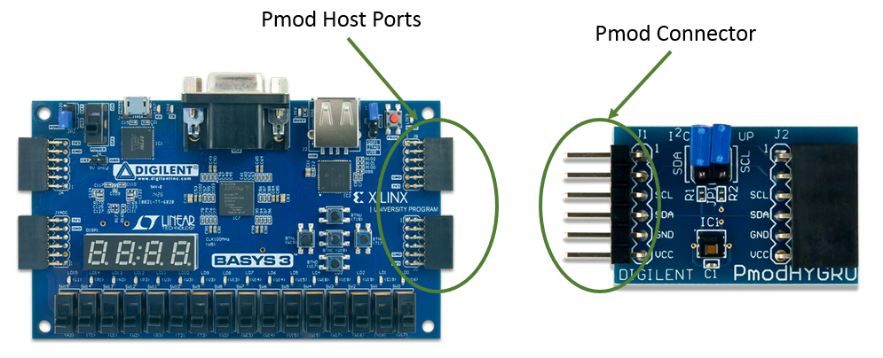
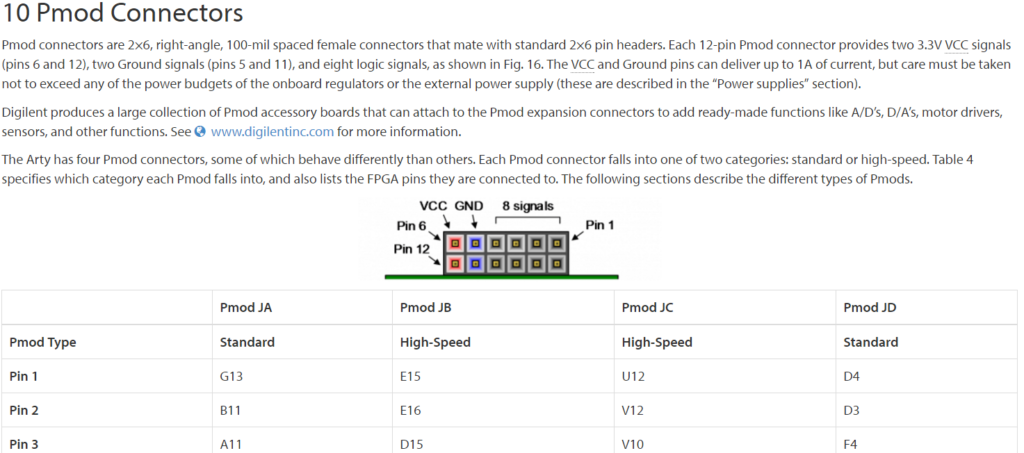
First, a couple of definitions. The male connectors on Pmod boards themselves are referred to as “Pmod connectors,” while the female connectors on host boards are referred to as “Pmod host ports.” The diagram below explains the distinction.
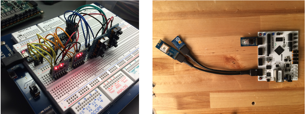
In general, there are three main ways to connect a Pmod to a host board in general. The first method is to plug the Pmod directly into a Pmod host port. The second is to use Pmod cables, which come in several varieties including 6-pin, 12-pin and 12-pin to dual 6-pin splitter cables. Lastly, Pmods can be wired up using MTE cables or individual jumper wires, which is necessary if the host board does not have enough Pmod ports built in. This last method is arguably the messiest but is still quite effective and a perfectly viable way to use your Pmod. In fact we do it all the time!
In terms of signals, the majority of Pmods use one of four different serial protocols: SPI, I2C, UART or GPIO. When using FPGA boards, the communication protocol is less of a concern when deciding which host port or which pins to plug into as each pin on the FPGA can be assigned to be whatever you need it to be. When working with microcontrollers it’s a different story, but that will be handled in another post. With these general considerations in mind, let’s start diving into the details.
I have a 6, 12 or 8-pin Pmod and want to use it with my Digilent FPGA board.
There are two main categories to consider when plugging in your Pmod, electrical connection and mechanical connection. We will break the two down:
Electrical
When considering the electrical connection, the first thing you’ll need to know is whether your Pmod uses digital or analog signals (99% of Digilent Pmods are digital). If you’re using a digital Pmod (which you most likely are) you can plug it into any Pmod host port on a Digilent FPGA board and it will work. This is regardless of communication protocol used by the Pmod (e.g. SPI, I2C, etc.).
One example of a digital Pmod is the Pmod Infrared Motion Sensor, which uses a simple GPIO interface to detect motion using passive infrared technology. It’s a great starting point for motion-activated projects like automatic lights, alarms, or occupancy detection.
What’s more, if you have a 6-pin Pmod, you can plug it into the top row or bottom row of the 12-pin host port. If your design permits, you can even plug two 6-pin Pmods into the same 12-pin host port, one on the top and one on the bottom. This is exemplified on the right hand side of Fig. 2.
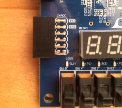
If your Pmod uses analog signals, you’ll need to look for analog capable host ports. You can easily identify this port by checking the silkscreen of your FPGA board. You should see a Pmod host port labeled “JXADC.” See the image to the right for an example.
The JXADC port is wired to the auxiliary analog input pins of the FPGA. Depending on the configuration, this port can be used to input differential analog signals to the analog-to-digital converter inside the on-board FPGA (XADC). Be sure to also check your board’s reference manual to make sure you’ve correctly identified this port.
Mechanical
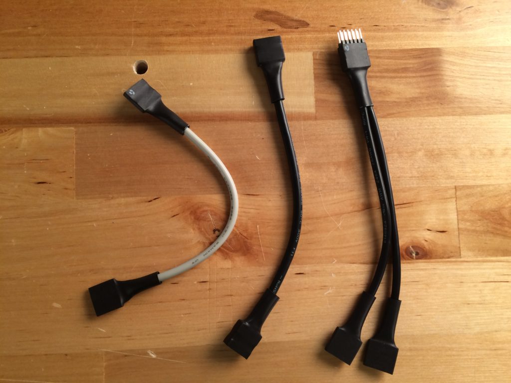
In terms of mechanical connection, as mentioned previously, you can plug directly into any host port, or cable connections can be used. We have 6-pin, 12-pin and 12-pin to dual six-pin cables specifically for this purpose. If plugging two 6-pin Pmods into a single host port, you’ll want to use the 12-pin to dual 6-pin splitter cable pictured in Fig. 2. Lastly, if you are trying to connect to a board without connecting directly to Pmod host ports (examples include using the shield headers on the Arty board, connecting 8-pin I2C Pmods, or connecting through a circuit on a breadboard), you can use Pmod CON1 connectors, MTE cables or jumper wires, also shown in Fig. 2. MTE cables can be purchased in packs of singles, or 6-pin, 4-pin, 2-pin, or other styles.
Special Considerations
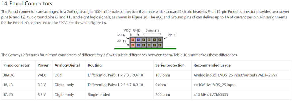
Although your digital Pmod will technically work with any host port on a Digilent FPGA board, there are considerations to make regarding high-speed ports that could improve performance. The high-speed Pmods use the standard Pmod connector, but have their data signals routed as impedance matched differential pairs for maximum switching speeds. They have 0-Ohm shunts in place of series resistors and therefore allow for much faster switching speeds, but offer no protection against short circuits. For this reason, we recommend these high-speed ports only be used if your Pmod requires data signals faster than 10 MHz, or if the standard ports have been used and additional ports are needed. In either case, caution must be taken not to use voltages higher than 3.3 V, or short FPGA-driven pins.
To identify these ports, check the FPGA board’s reference manual. The high-speed ports will either be labeled as such directly, or will be identified as having 0 Ohm series protection. Series protection is very important, to so make sure to note which Pmod ports have it and which don’t. See the images below for examples.
So to sum up, if you’re using a Digilent FPGA board it’s really quite straightforward to decide where to plug in your Pmod. First, ask yourself if it is digital or analog. If it is analog, you need a JXADC port. If it is digital, ask whether or not it operates faster than 10 MHz. If it does, then you should use a high speed port, but if it does not then use any standard port. Easy as that!
For any questions or comments, please use the comment section below or visit the add-on boards section of the Digilent Forum!
Dear Talesa,
I am working with a Nexys 4 DDR and was wondering, if it has any high-speed ports? According to the documentation, all ports have a 200 Ohm resistance. There is no indication of a high-speed port. Can you confirm?
The thing is that I need to process a 200 MHz digital signal. I guess that the Nexys 4 might be the wrong board for this purpose..? Or can I upgrade with a PMOD?
Also, I have a question regarding the input format of a digital signal. Is there any requirement for the format? The above-mentioned signal would be a 0…-400 mV signal rectangular signal.
Thanks and best regards,
FZ
You are correct, there are no high-speed ports. For the second half of your question, if you do not mind heading over to the Forum to post there they can help you with the more technical details, and then others who might have the same questions can benefit!
Hello
Is it possible to send external signals (0v for bit 0 and 3.3 for bit 1) through the pmod i/o pins? I’m working on a school project where i’m connection 4 outputs from my circuit to the pmod pins on the basys3. This outputs signals are either 0 or 3.3 to represent the bcd combination from 0000 to 1111.
I’m not able to find MISO and MOSI pins in nexys A7 fpga board
can any 1 help me out
Dear Talesa Bleything,
Thank you for your clear explanation. I’m new to FPGAs, I bought a Nandland Go Board to learn hardware programming and do a project that requires connecting a camera to the board.
The first thing I struggled with was finding a camera I could use with the limited ports available on the board. As mentioned on their website, the Pmod host port is created by Digilent Inc.
your support is higly appreciated.
BR
YG