

 Announcing the addition of the Pmod CAN to the Pmod communication family!
Description
Controller Area Network (CAN) is still a widely used communication protocol, especially in the automotive industry. Therefore, instructors must teach CAN to their students. After getting asked by many different instructors about whether or not we had a Controller Area Network Pmod, we went ahead and designed one.
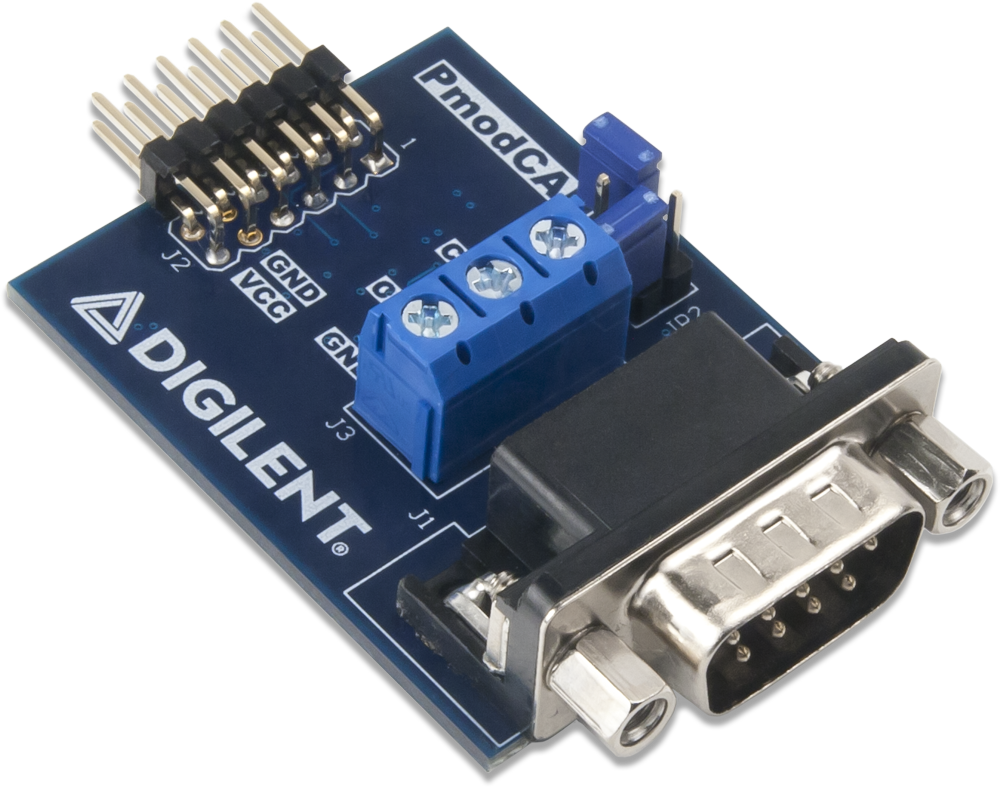
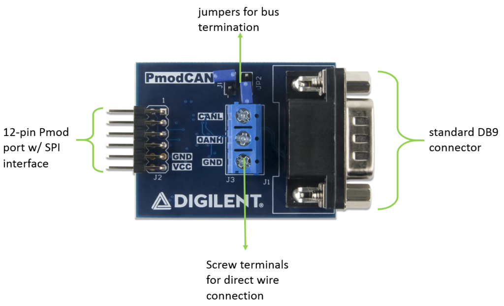
The Pmod CAN utilizes the Microchip MCP25625 to enable CAN communication with a variety of external devices. A complete CAN solution with a controller and transceiver can be implemented on a system board by communicating with the host board via the SPI protocol in SPI mode 0 or 3. The two differential lines on the transceiver (CANH and CANL) enable balanced differential signaling to eliminate most of the electromagnetic field (EMF) and provide high noise immunity within the system.
How does is work?
CAN is a peer-to-peer networking protocol. This means there is no single master controlling the flow of data between nodes on the network, such as there is with something like the SPI protocol. Instead, any node can write a frame to the network anytime the bus is free. All nodes on the network will receive the transmitted frame and decide whether or not to accept it based on what is called an arbitration ID. If multiple nodes try to transmit frames simultaneously, the node with the highest priority (lowest arbitration ID) will get bus access. For more information on CAN protocol in general, see this whitepaper from National Instruments.
As stated above, the Pmod CAN communicates with the host board via the SPI protocol. By driving and keeping the Chip Select line at a logic level low, users may communicate back and forth with the Pmod, depending on whether or not both sets of data lines are enabled. The embedded chip on the Pmod operates in SPI Mode 0 or 3, with data captured on the rising edge of the clock, data transferred on the falling edge of the clock, and a minimum clock cycle time of 100 nanoseconds.
Nine SPI instructions are available to read the status of the receiver, load a transmit buffer, modify bits in a register and more.
Applications
As mentioned in the intro of this post, CAN is most well known for its use in the automotive industry, specifically for in-vehicle communication. However, it has also been adopted by other industries due to its benefits as a low-cost, lightweight, dependable and durable wired networking standard. This includes use in railway applications, aircraft, aerospace, medical, as well as elevator and escalator applications to name a handful.
The Pmod CAN is designed to work with any Digilent FPGA, Zynq or MCU board. It can be plugged into any host port on a Digilent FPGA or Zynq system board. With Digilent microcontroller boards, a little more care needs to be taken to figure out which Pmod host port supports the SPI protocol. Once identified however, the Pmod CAN should be easy to get up and running with any Digilent MCU board. Just follow the Quick Start section of the reference manual to get started!
Getting Started
If you are an MCU user, we’ve written some libraries and example code to illustrate how to start communicating using the CAN protocol. The example code was written in the Arduino IDE and should work smoothly with the Digilent core for Arduino. For download instructions, see our tutorial on how to get started with the Digilent core.
If using the Pmod CAN with a Digilent FPGA board, see our wiki page titled Using Pmod IPs for instructions on how to use our drag and drop Pmod CAN IP Core with MicroBlaze designs.
Questions or comments? Use the comment section below or visit the Digilent Forum!