

Welcome back to the Digilent Blog!
Here at Digilent we have a ton of products with a large amount of documentation and examples (like our Learn site and our Instructables page) letting you know how you can use our products. Within all of these, there are statements about what each product is (and is not) capable of in addition to the recommended operating condition. Some of you may be wondering, “How do we know these things?” Much of the information presented is determined from a datasheet. But where do we find this sort of information in the datasheet, or how do we even read a datasheet? Let’s find out.
Datasheets can be pretty daunting to a relatively new member of the electronics world, and therefore not everything in the datasheet has meaning for me. Instead, I have to be able to sift through the information and find out the relevant pieces to whatever project I am doing. However, this precludes one knowing what a “relevant piece of information” is in the first place. Luckily, even if we don’t know anything about our device, there is a way to read the datasheet efficiently to find out what we need to know. I’ll show you how with the PmodDA4, although this technique can be applied to any datasheet.
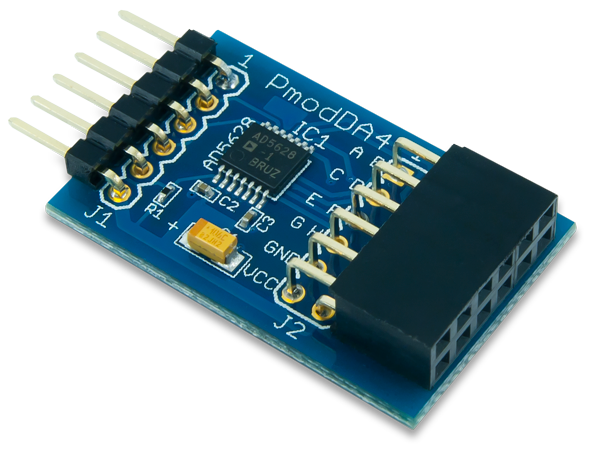
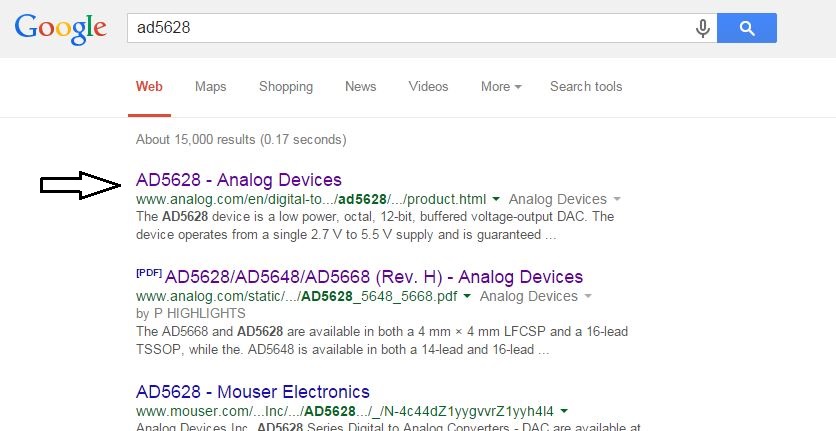
Taking a “bare bones” approach with the presumption that all we have managed to do is set the PmodDA4 on the table in front of us, there are two ways we can figure out what datasheet we should be looking for in the first place. The datasheet will not be for the Pmod itself, but for the small, black integrated circuit (IC) that we can see on the top of the Pmod. Knowing this, we can either read on the chip that it is a “AD5628” or go to the PmodDA4’s product page on blog.digilentinc.com to see that the Pmod was “engineered around the Analog Devices ‘AD5628’ digital-to-analog converter.” Now that we know what the IC is, we can then “Google” the part name “AD5628” and go to the link that appears from www.analog.com.
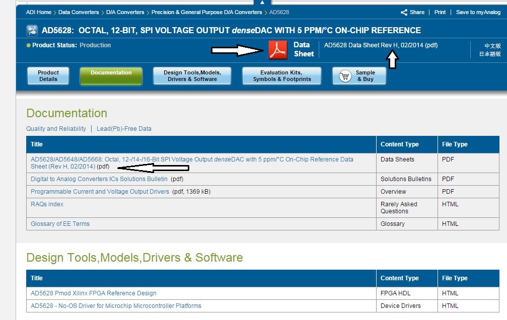
Once here, there are several different ways of actually downloading the datasheet shown in the picture below. It does not really matter which link you choose, although the bottom-most option is the most descriptive.
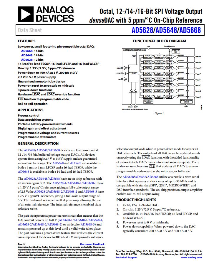
This brings us to what we have been waiting for (or dreading)–the datasheet itself. Before we go any further, I want to remind you that we are just looking for certain things in order to successfully operate the PmodDA4. This means that I will end up skipping over many of the graphs and tables within the datasheet. However, this is not to say that those things are not important; they are just not relevant to my specific application.
Moving on, there are four things that I always look for in every datasheet: the features, the general description, pin descriptions, and a theory of operation. The features and general description give us a quick overview of what the device does and tend to be conveniently located on the first page of the datasheet. The pin descriptions and theory of operation sections will give us a little more detail about the device and are a great way to let us know if there is something else in the datasheet that we might need to look for. The locations on these sections can easily be found in the table of contents.
If we take a look on that first page of the AD5628 we can see, as expected, a list of features and a general description. This nicely leads us back to the original problem: how do we know which pieces of information are relevant? I look for things that are specific to individual components within the device as opposed to the device as a whole. I feel it is more useful to know how many bits the device communicates with and what communication protocol it uses to communicate that data, as opposed to the fact that a device is monotonic or that you can reset the device to 0V or midscale. In a sense, I only look for things that are strictly related to my application (in this case, the digital-to-analog conversion).
With this in mind, we can look over the first page on the datasheet and find some helpful things for our (or at least my) DAC application. The datasheet explains that the AD5628 has a 12-bit output and that it uses SPI to communicate information. Because SPI is designed to operate in 8-bit chunks, this implies that multiple bytes will be sent from this Pmod that do not directly relate to the 12-bit output. There are also a couple of things that indicate that they need to be looked into more, such as the mentioned “external reference vs. internal reference” in the general description as well as the fact that we can get certain DAC channels to update simultaneously. I ignored some of the details, such as the fact that it is a 14-TSSOP or that there is a power down feature, since this component is already on a Pmod I can presume it is hooked up correctly. Also, I am not very concerned about power consumption, so I have no need to use the shutdown mode on this Pmod.
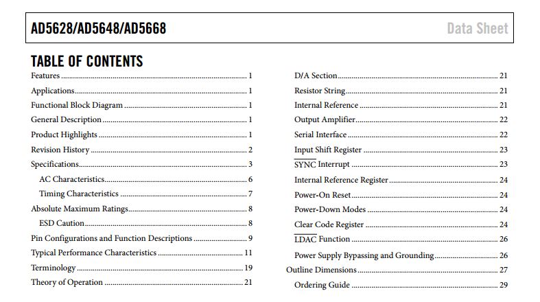
I then look at the table of contents, keeping in mind to look for extra details on the external vs internal reference and updating DAC channels, in addition to the pin descriptions and the theory of operation. We can see that there are a couple of sections dedicated to the internal reference as well as LDAC, so we’ll be sure to go to those sections unless something comes up. Now, we can jump to the pin configurations and function descriptions section since that is the next section of interest that is listed in the datasheet.
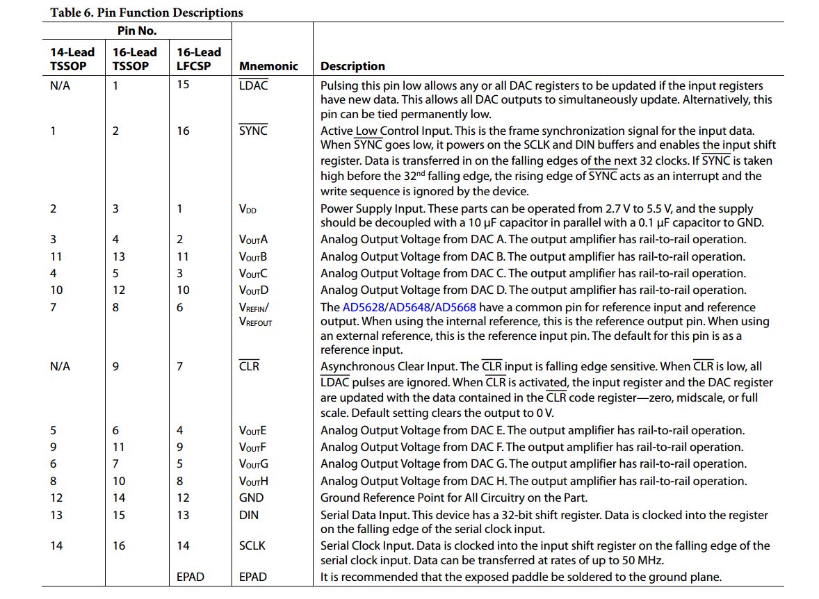
Within the pin descriptions, we can see that there are options for three different package types of this particular device. So, we can look back over at our Pmod and see that they AD5628 that we have only has 14 pins, meaning that we do not have to worry about the LDAC or the CLR pins. We can also see that there are 8 different digital outputs, 3 SPI pins, as well as a voltage reference pin. The description for the voltage reference pin describes this pin to be looking for an external reference by default; this tells me that I should look at the schematic for the PmodDA4 to see if this pin is already hooked up to a reference voltage for me.
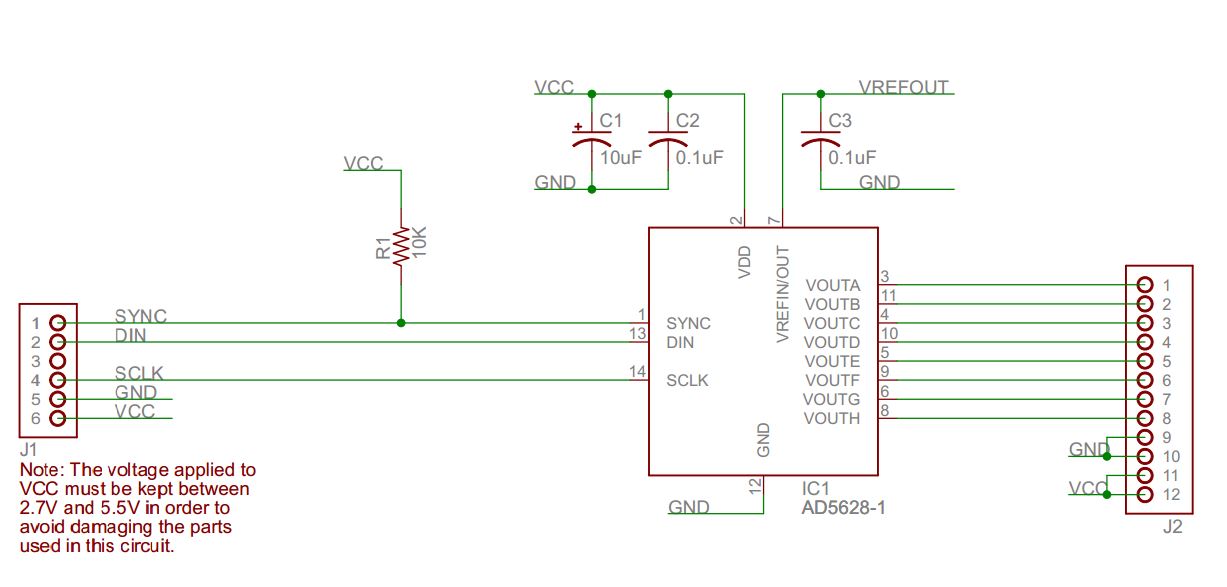
Unfortunately, the schematic above just shows that this reference voltage pin is connected to an undescribed “VREFOUT”. In essence, this means that we as the user, would need to apply an external voltage to this pin in order to have this reference voltage. But when I look at the PmodDA4, the idea of securing an external voltage onto one of those tiny pins is incredibly unappealing. This lets me know that it will be worth our while to check out how we might use the internal reference voltage that has been mentioned elsewhere in the datasheet.
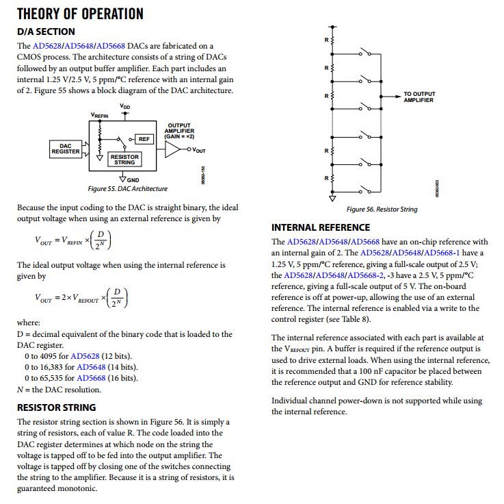
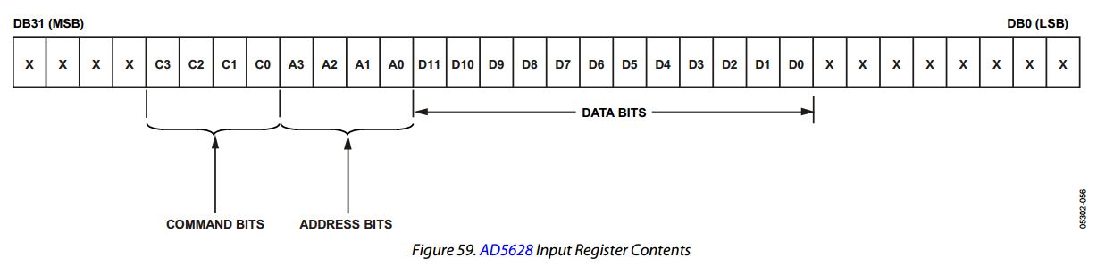
We can now continue onward to the theory of operation section. Once we reach this page, we see that the theory of operation is actually a main header with multiple sub-headers, including the internal reference section. Again, I tend to only read the sections that pertain directly to my application (using the DAC) or things that I decided I should look into more. With this in mind, we would first want to check out the D/A, the internal reference, and the serial interface sections. From these sections, we find equations for the output voltage and, after checking the Pmod schematic again, that using the internal reference voltage will allow for a maximum output voltage of 2.5V. The serial interface section also indicates that this device communicates in 32-bit chunks, implying there is a lot more information that needs to be given to the device than just the 12 bits of data. Indeed, tables 8 and 9 indicate that we would need to give the device a 4-bit command as well as a 4-bit address in addition to the 12 bits of data. If we continue to scroll down through the theory of operation section, we can see the needed 32 bits of information that the AD5628 requires to operate.
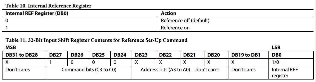
However, that still does not tell us how to “turn on” the internal voltage reference. Luckily, on the next page we see the section internal reference register which indicates that we need to use a certain command and turn a certain bit “on” or “off” to use the internal voltage reference, with a hint to look at Table 10. Scrolling down to Table 10, we see that the last bit needs to be at a high voltage to use the internal voltage reference and can also see in Table 11 the 32 bits that we would need to send to the chip on the PmodDA4 over SPI. We can then browse through the rest of the sections, but since I am not intending to go into the shutdown mode and cannot use the LDAC or CLR anyway, I now know (or at least know where to find) everything that I need in order to successfully operate the PmodDA4!
Despite having successfully gone through a datasheet and maintained our sanity, this still leaves a question. Why all this trouble with datasheets in the first place? While I do not believe there is a specific answer, I think Analog Devices did a good job on summarizing the main sources of trouble with datasheets inside a big company in one of their RAQs:
The IC designer who writes the first draft of a data sheet wants to emphasise the genius of his or her creation. The marketing manager wants to stress competitive advantages of the product while soft-peddling any drawbacks. The test engineer wants to minimize the time and cost of production testing, and tries to remove all maxima and minima from the table of characteristics, instead replacing them with “typical” values. Corporation lawyers want to make certain that potential (mis)users of the device have no grounds for suing the Corporation. Corporate communications wants the document shrunk from 60 pages to four. And applications engineers (ahem!) want the data sheet so clear and simple that even a software engineer can understand it and they can sleep away their afternoons without the applications enquiry phone ringing. The final product is a . . . compromise, and not always as helpful as it could be. And because data sheets are always produced in a hurry when the product is ready for release they always have some mistakes.
As a user of datasheets, it’s not terribly helpful for anybody (including myself) if I just complain about them. It’s much better if I can just skim through a datasheet in a similar method to what I showed above and learn what I need to know for my project. Inevitably, my method does not account for everything about the device; much of the information I can safely ignore based on my projects capabilities and application. But, also inevitably, not every project can get away with doing that.
Do you have any other handy tips for reading a datasheet?
how to know the sampling rate for DAC in datsheet
I wish you could make a post explaining the meaning of those abriviations the “DAC” etc and there function in a less technical language so that even students can understand. Thank you
Thank you. There are so many EE-centric pages about how to read a datasheet, and not as many for SW engineers.