

Welcome back to the Digilent Blog!
A while ago, we learned that one of the ways that Pmods are able to communicate with their host board is through SPI. We learned then that serial peripheral interface is a type of communication protocol where the “master” board and the “slave” device (in this case, a Pmod) are able to send bits of data to each other at the same time with the host board controlling the timing of the communication. Although this is a nice overview, it is my personal experience that theoretical overviews are not the most helpful in actually implementing what we are learning. This begs the question: how do you use SPI? Lets find out!
On a fundamental level, all electronic devices operate and do different things based on what voltage signal they receive (either a high or low voltage signal). The serial peripheral interface sends these same high and low voltage signals in a serial (sequential) fashion. The difference between SPI and using a simple “switch on” and “switch off” signal is that SPI sends eight of these “on” and “off” signals (bits of data) all in a row. These eight signals allow for a more precise output (as opposed to fully on or fully off), allow multiple outputs to be affected (more or less) simultaneously, allow a specific action from a set of options to be performed, or a combination of all of these. Furthermore, all of these things can happen in both directions–to the master and to the slave device, at the same time. Essentially, SPI allows for the electronic devices’ user to operate them with more finesse.
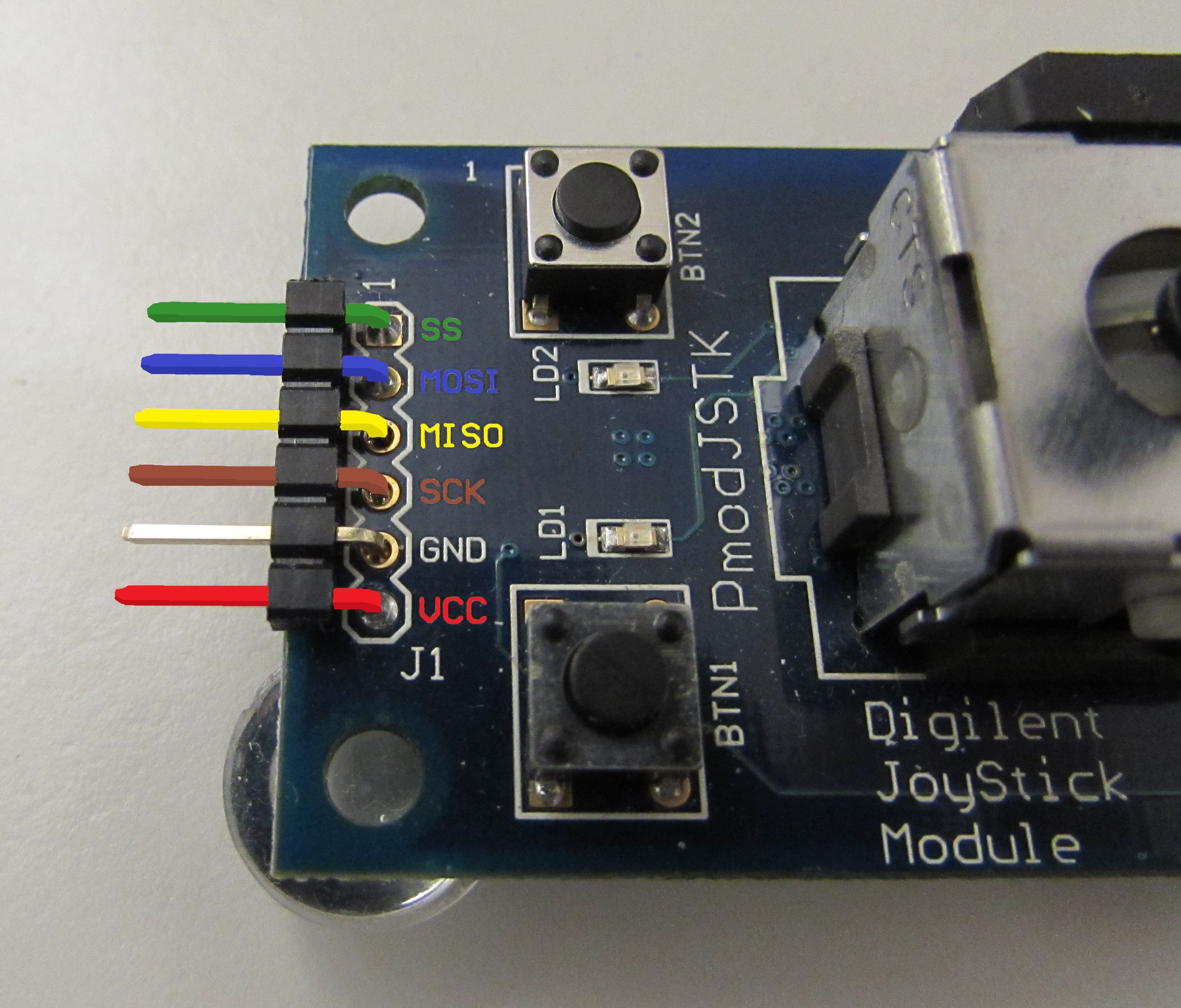
To operate with more finesse, more wires connecting the two communicating devices are required. SPI uses four wires: a chip select wire (CS, or SS for slave select) to indicate to the “slave” device that it is going to have a conversation with the “master” device, two data wires, Master-Out-Slave-In (MOSI) and Master-In-Slave-Out (MISO) for the data to travel to the slave device and from the slave device, respectively, as well as a serial clock wire (SCK) which the master “pulses” to control the rate at which the communication between the two devices occurs. On Pmods, the SPI pins are arranged with the CS wire in the pin 1 position, then the MOSI, MISO, and SCK lines. A final pair of power and ground lines make the Pmods which use SPI a 6-pin peripheral module.
In general, many of the details behind the SPI protocol can be handled by an SPI library. However, I personally feel that having an understanding of what is happening within a library and being able to replicate it with your own code is very valuable and more helpful in the long run.
When setting up your system with SPI devices, you might find it useful to consider using Pmod CON1: Wire Terminal Connectors for a more secure and organized way to make connections. These connectors allow for easy wire management and ensure stable connections for your Pmods.
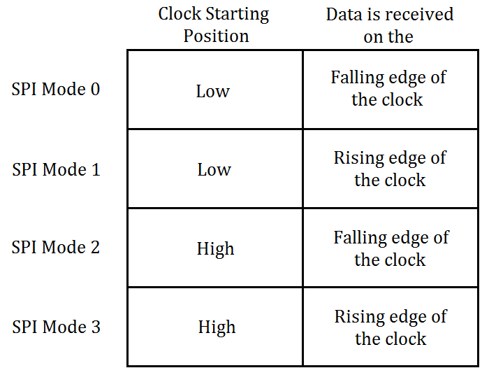
But back to SPI! The “pulsing” of the SCK line is done by having the master oscillate the voltage of the wire between a logic high voltage and a logic low voltage. One of the eight bits of data with either the most significant bit (MSB) or the least significant bit (LSB) transferred first, are placed onto the appropriate data line by both the master and the Pmod (the slave device) by bringing the wire to a high or low voltage, and are then received by the opposite device depending when the slave device expects to receive the information. The receiving of information can happen when the serial clock is transitioning from a low voltage state to a high voltage state (the rising edge of the clock) or the falling edge of the clock (high to low voltage state). These transition states, along with what voltage level the clock starts at, make up what are known as the SPI modes, shown in the table below. SPI mode 0 is one of the more popular modes that is used; this is why it is at the top of the list.
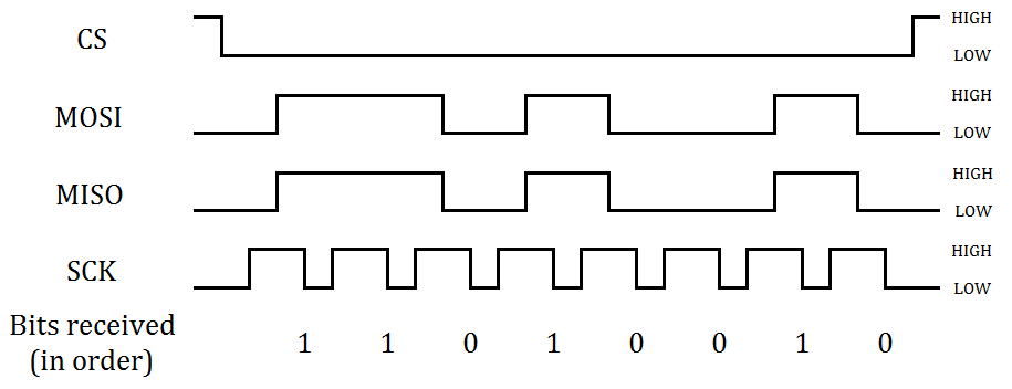
So, if a master and slave device are to send each other a value of 210 (11010010 in binary, where the 1’s represent a high voltage signal and the 0’s represent a low voltage signal) where the slave device needs to receive information on the falling edge of the clock with the clock initially starting out in a low voltage state and the data is to be sent MSB first, the following sequence would need to occur. The master device would first bring the appropriate CS to a low voltage state. Then, the SCK line will be brought to a high voltage state to prepare the clock. The master device will then bring the MOSI line to a high or low voltage state as appropriate and the slave device will do the same (on its own since we as the human users generally do not directly control what the slave device puts on the MISO line).
After bringing the data lines to the appropriate voltage level, the master will bring the the SCK line to a low voltage level, allowing the both the master and slave device to receive data on the appropriate data line. After this pulsing of the clock line and the sending of data has occurred a total of eight times, the master will then bring the chip select line to a high voltage level to terminate the conversation with the peripheral module. You can see a visual representation of this process in the picture just below this text.
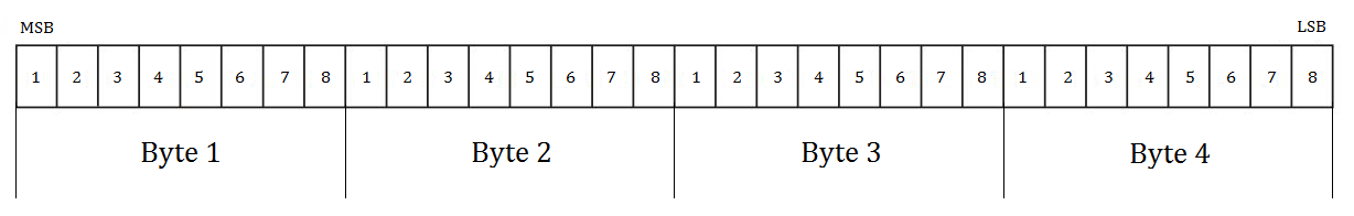
In the SPI protocol, you are only able to send 8 bits (1 byte) of data at a time, without exception. So what do you do when you encounter a device, such as Digilent’s PmodDA4, a DAC, which takes 12 bits of data via SPI? The first thing I recommend to do is not panic–it was designed this way. The second thing I would do is check out the datasheet for the Analog Devices AD5628 chip which the PmodDA4 uses. After a bit of searching, we can find on page 22 that we are not sending just 12 bits of data, but 32 bits of data. These 32 bits can easily be split up into four bytes, allowing SPI to work as it was designed.
But while being able to send data from one device to the other is vital, so is receiving the data. We generally don’t worry about the slave device receiving data because, again, we as users do not always have direct access over what the device sends and receives over SPI; that tends to be handled internally by the chip on that device. Although the master device does not always need to receive data from the Pmod to have the module work correctly, sometimes the master device does need to receive information from the Pmod, much like you would need to if you were receiving input from the PmodJSTK. (If you’re looking for other types of input devices for your project, consider adding sensors like the Pmod PIR: Passive Infrared Motion Sensor. This sensor can be easily integrated with your setup for motion detection applications.)
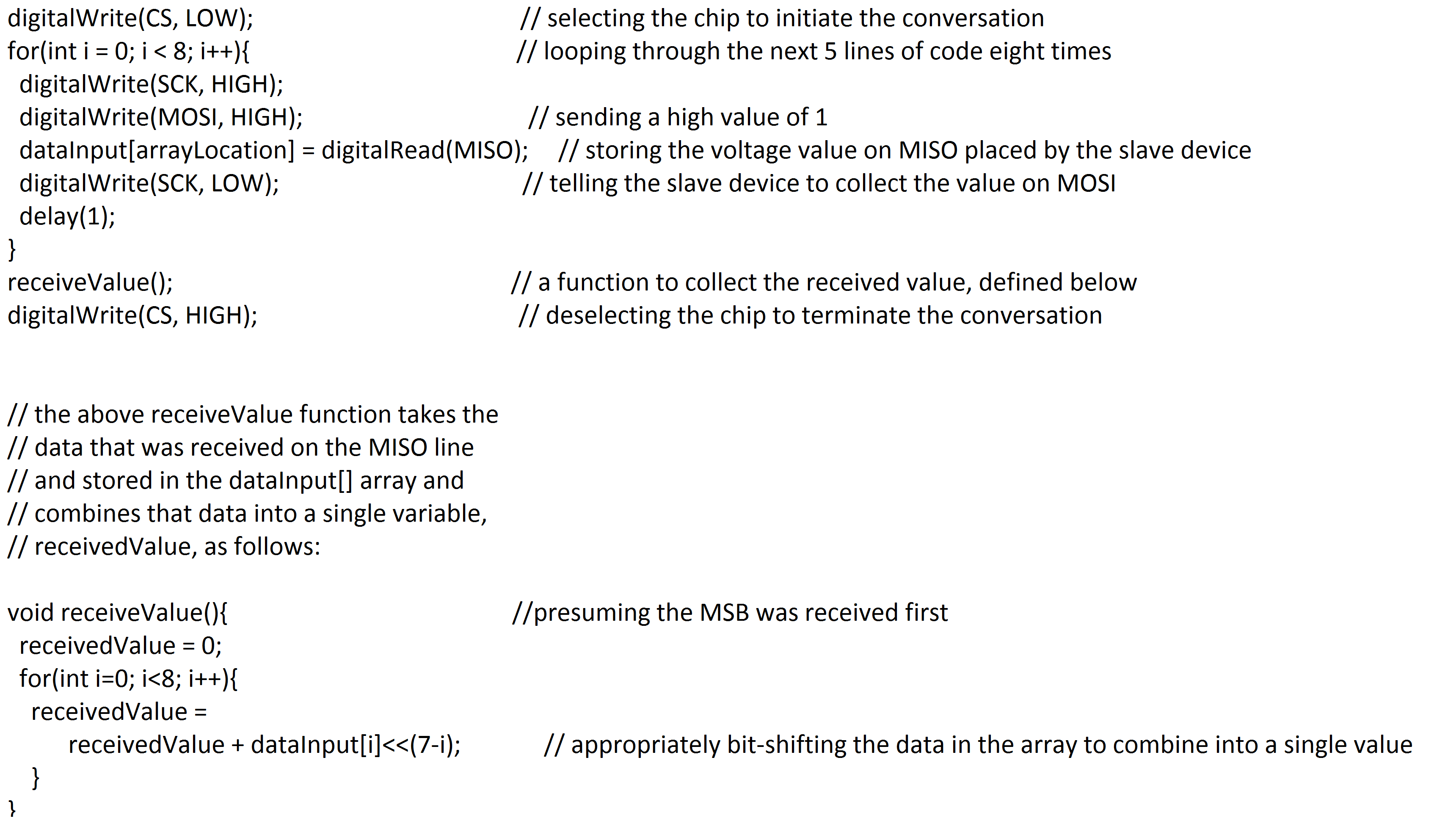
The information can be received in one of two ways. If you are manually sending the bits of information and controlling the clock through code, you can use an array to store each bit of information after the data has been transferred by the slave device and then access the data later to appropriate decipher it. With a library, such as the DSPI library designed by Digilent, the bits of data are still collected and stored individually, but you are then able to access all of the bits as a single byte after the information has been transferred.
You can check out an example of how SPI might look in code below.
Check out the rest of our Pmod series and come back soon for more!
4 Comments on “Pmod Communication: Serial Peripheral Interface”