

Any student that takes any sort of digital design class will learn about multiplexers (muxes) early in their studies. At Washington State University, students learn about muxes in EE214. EE214 is a class that students in electrical or computer engineering generally take in their first or second year of school that covers introductory FPGA design.
A huge part of FPGA design is using logic blocks in design. With logic blocks, you can compartmentalize your design, rather than trying implement everything in one shot. Designing without smaller blocks would be like trying to design a car without subsystems like the braking system or engine. About half of the way through the course there is a project that covers a variety of basic logic blocks, including muxes and demultiplexers (demuxes). A mux is one of the more recognizable logic blocks simply because of its block diagram.
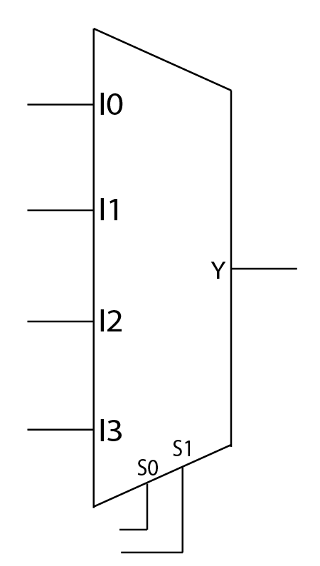
The block diagram allows users to design large designs using a mux without having to worry about the logic inside of it. All they have to worry about is what it does. So what does it do?
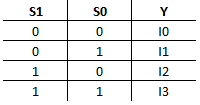
The easiest way to think about a mux is that it is an input selector. Based on the select code you apply so the S inputs, it will connect only one input to the output. For a more formal definition, I’ve presented a truth table. A truth table shows all the possible outputs of a circuit for every possible combination of inputs.
You can also think of a mux as a switchboard. You are the output Y and the operator is the mux. Depending on the extension (S inputs) you give the operator, you will be connected to a different person (I inputs).
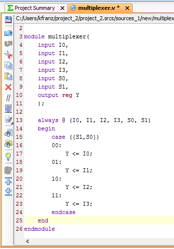
For those with a coding background it may be better understood in code. Muxes are built off of case statements. In Verilog, a mux would look like this:
Now what is a demux? You can think of a demux as sort of the opposite of a mux. Instead of routing one of four inputs to 1 output, it takes one input and routes it to one of four outputs. Here is the block diagram of a demux.
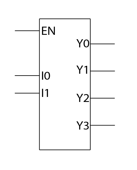
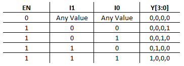
The signal EN is the input that you are trying to pass, and I0 and I1 create the select code for the output that you want to pass it to. If you want to pass a 1 to Y1. Then you need to hold EN high at a 1 and pass a 0 to I1 and a 1 to I0. In binary 01 is equivalent to 1, so if you want to select an output, pass the binary value to the I inputs.
To clarify, here is the truth table for a demux:
If you would like to see a mux in action you can visit learn.blog.digilentinc.com and try out the Multiplexer Guessing Game (using the Uno32) and the simple communication system (using FPGA) projects.