

Welcome back to the Digilent blog!
This guide walks through the entire process, start to finish: getting the required files, creating the Vivado project, writing the Verilog and XDC code, and generating and programming the bitstream.
While it would be nice to think that we can simply write up an FPGA program and configure our board with it and move on to the next program, FPGAs are complex enough that it is a good idea to add in some pre-made board files to help smooth out the programming process. I will be using Digilent’s Arty throughout the duration of this tutorial and Verilog as my FPGA programming language of choice and the 2016.4 WebPACK edition of Xilinx’s Vivado Design Suite, though boards like the Basys 3, Nexys A7, Cmod A7, Cmod S7, and Arty S7 will also work.
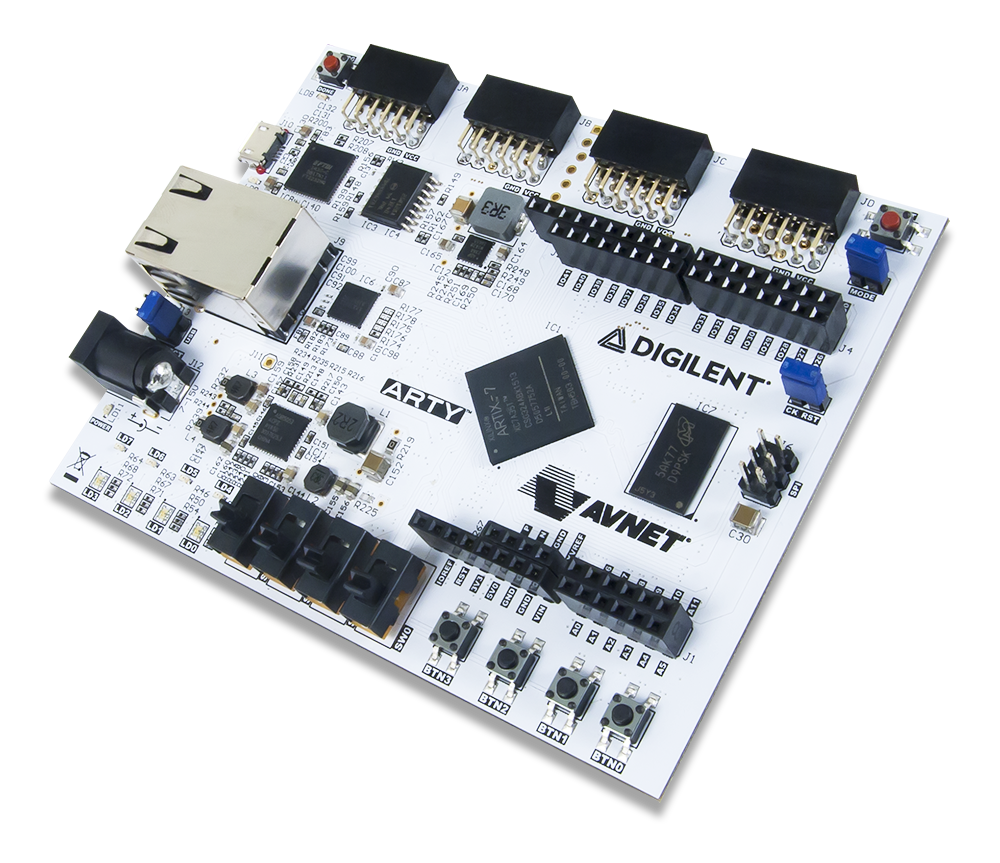
The two files we will be looking for are the Arty XDC (Xilinx Design Constraints) file and the Arty board file. The XDC file is used by Vivado to associate the names of the inputs and outputs we “create” in our Verilog code to actual pins on the FPGA chip. The board file is used to group different sets of pins on the FPGA together so that they can be readily used when configuring various IP blocks; we won’t be using any IP blocks in this tutorial, but it’s nice to already have the board file installed for the future (and makes it much easier to tell Vivado which FPGA we are working with when we are initially creating a project).
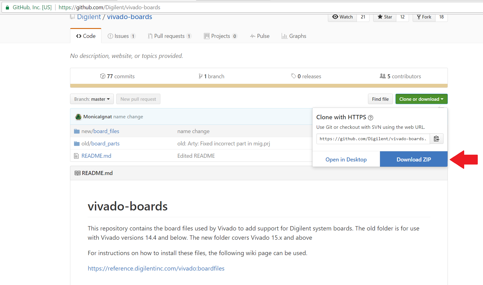
To get the Arty board file, go ahead and download the Digilent board files from the Digilent GitHub account (at the direct download link or view the board files natively in GitHub here). Within the board files .zip folder, you’ll want to extract the “Arty” folder (and everything inside it) to the board_files folder that is inside the Xilinx directory, which you already have installed. On a Windows system, the default location for this board_files folder is C:\Xilinx\Vivado\2016.4\data\boards\board_files; copy the whole “Arty” folder structure into this folder.
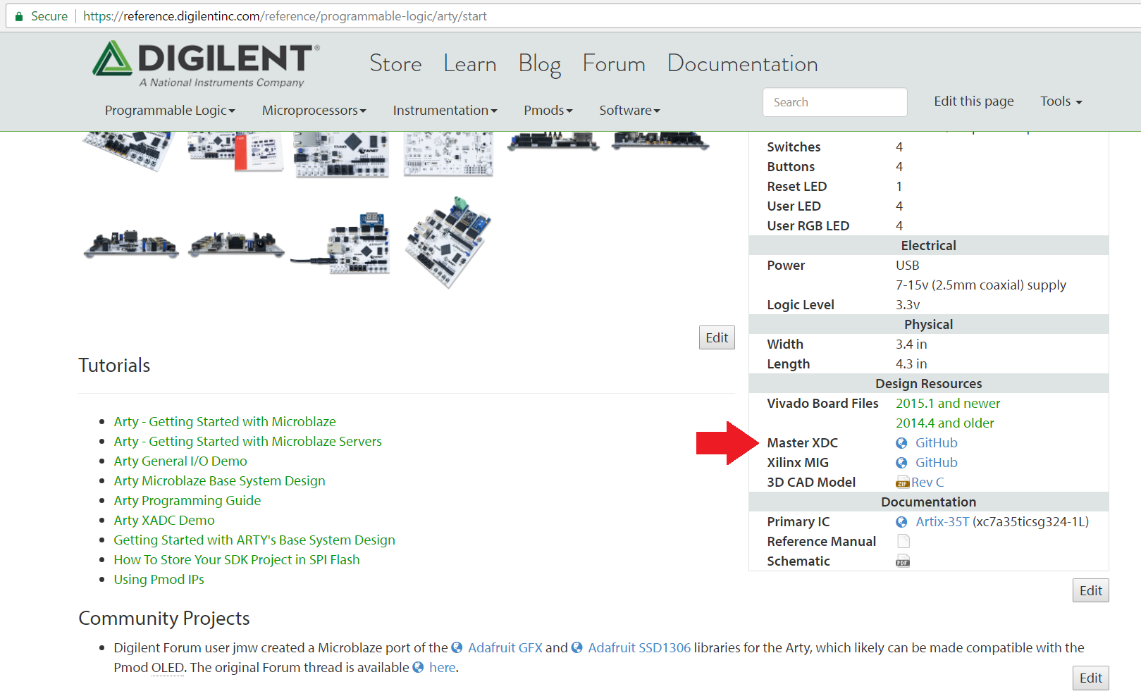
Next, we’ll want to get the XDC file for the Arty so that we can inform Vivado what physical pins we wish to use with our project. A master XDC file for the Arty (and all of Digilent’s FPGA boards) can be found in their respective Resource Centers on our Wiki. The Arty Resource Center is here, with the Master XDC file available in the box on the right-hand side of the screen underneath “Design Resources”. Once you have downloaded the Master XDC file, save it somewhere on your computer where you can easily find it again since we’ll need to be able to tell Vivado where to find the file when we create our project.
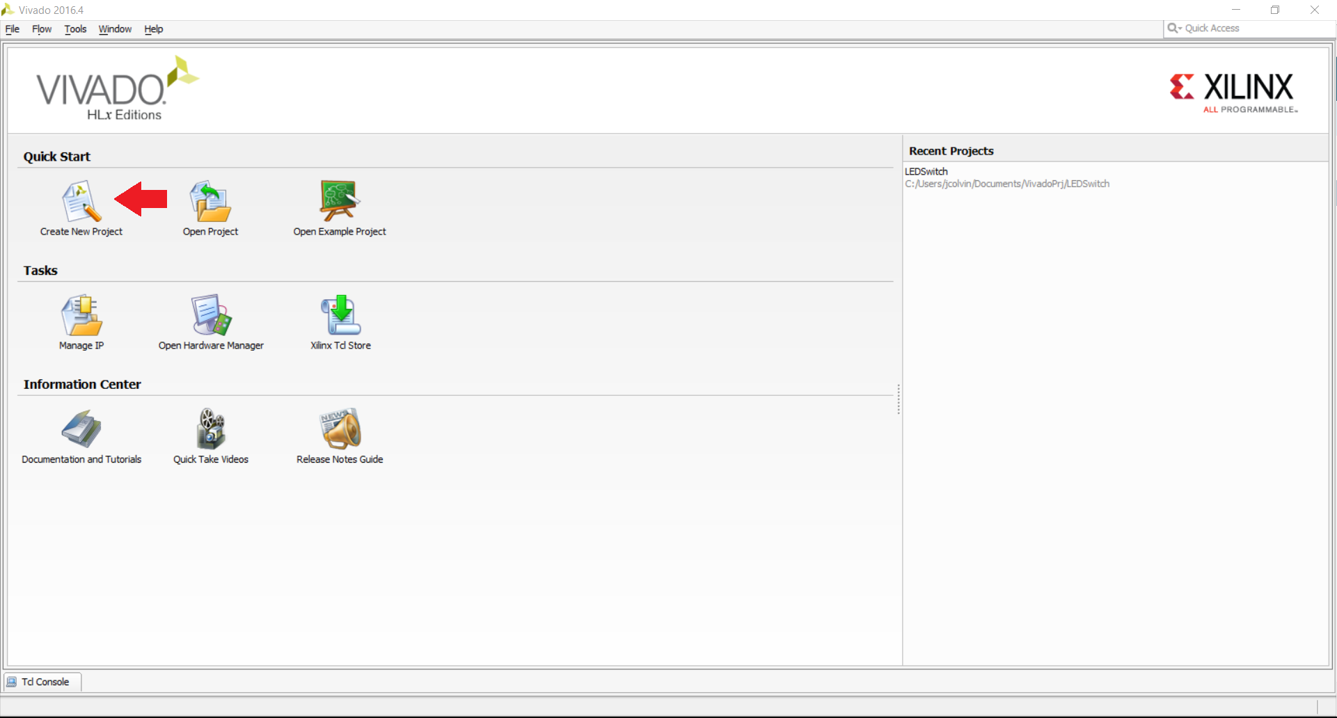
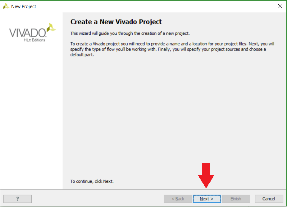
Let’s go ahead and create ourselves a new Vivado project. To do so, open up the Vivado application and click on the “Create New Project” button located in the upper left-hand corner, and then click “Next” on the next screen that appears to confirm that we do want to create a new project.
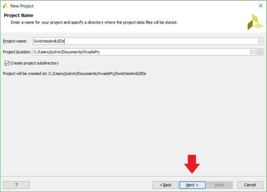
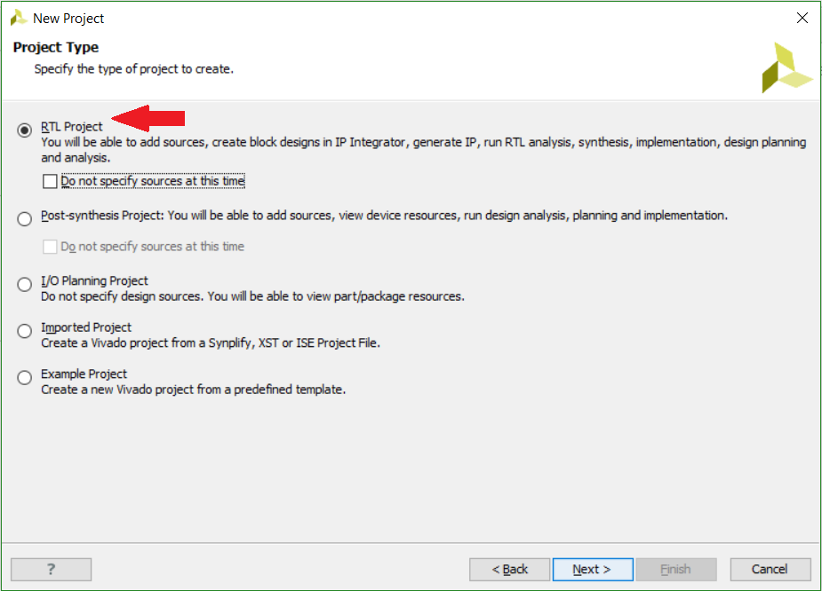
We’ll then be able to name our project and choose where we would like Vivado to save and generally store our project on our computer. The big caveat here is that both the name of our Vivado project, as well as the file path that our Vivado project is stored in, must not have any spaces in it. Otherwise, you will run into some issues when Vivado is trying to create a project. Once you have chosen your name and file location, click “Next”, and on the next page choose to create an RTL project (the first option), leaving the box to “Do not specify sources at this time” unchecked.
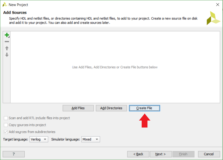
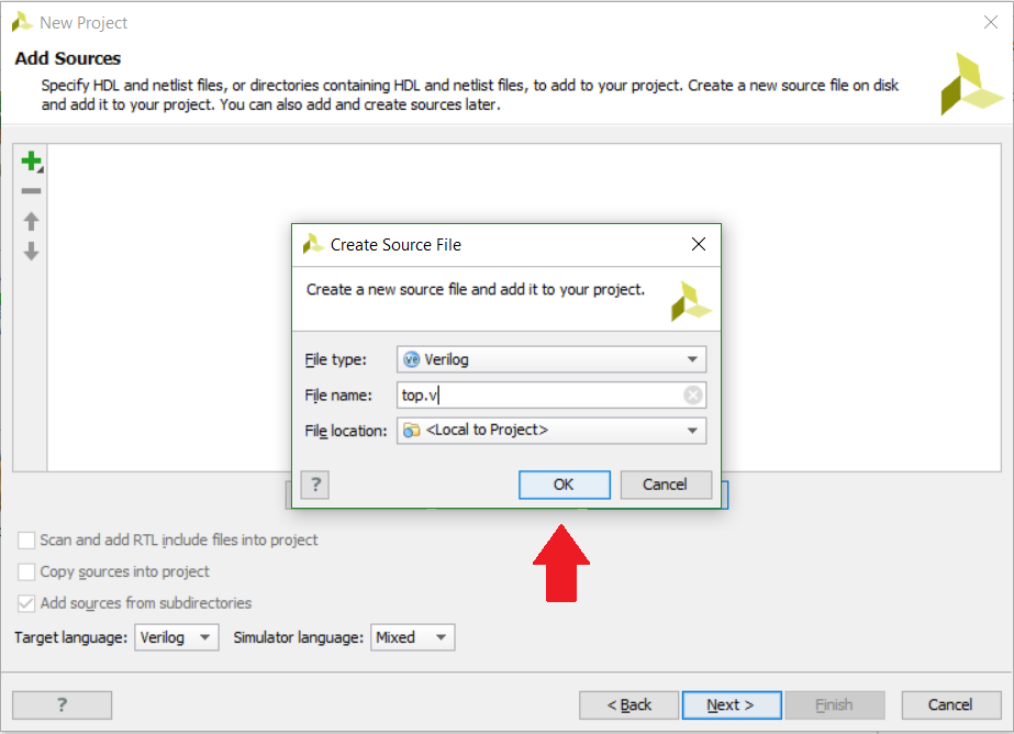
On the next page, choose “Create File” so we can create our own source file now rather than having to manually create it later. A “Create Source File” window will pop up where we can choose our file type of Verilog (for this tutorial) and the name of our Verilog source file. A typical name for these source files that will be the primary file that runs our program is “top.v” to signify that it is the file that runs (and calls) everything involved with that file. Once you’re done with that, click “OK” and then click “Next”.
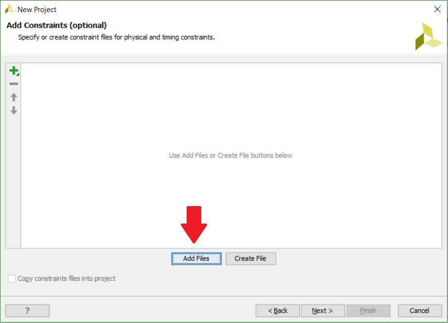
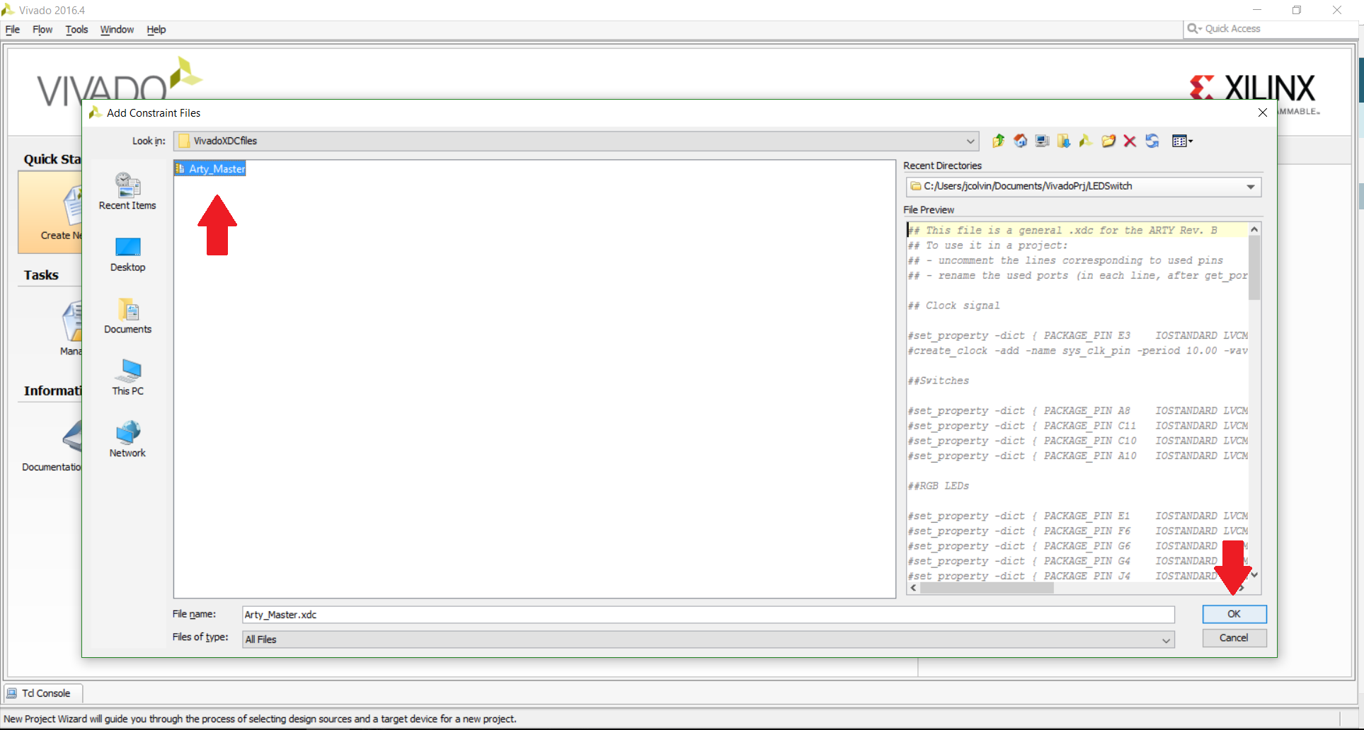
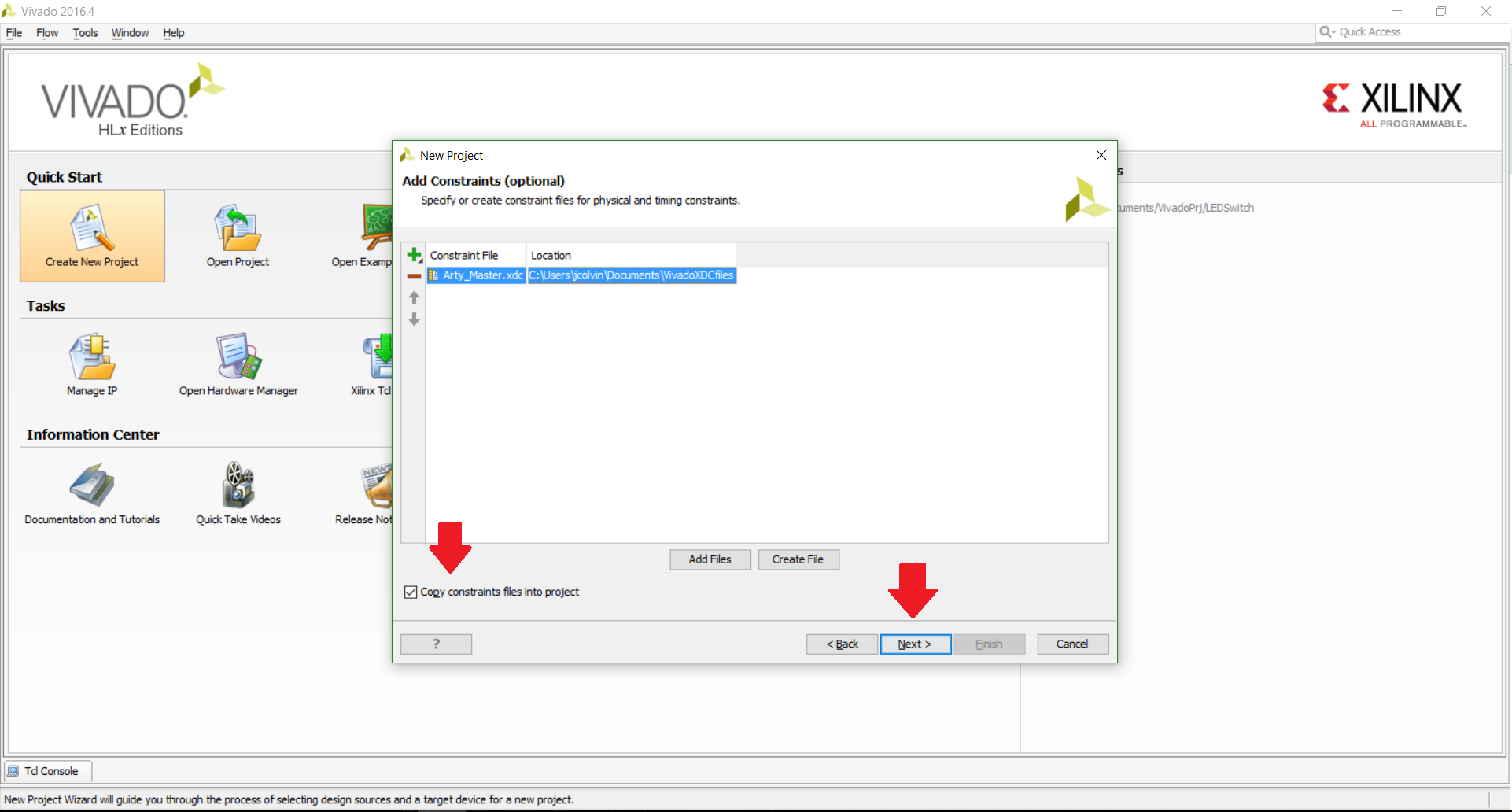
Go ahead and click “Next” on the page asking about IP cores since we don’t have any to add for this tutorial. On the next page for Add Constraints, we will want to choose to “Add Files”; the file we are looking for is the Master XDC file that we added previously. Once you have found and chosen this file, be sure to check the “Copy constraints files into project” box so that the original file does not get altered when we change it later on in the tutorial.
Now we’ll need to select the FPGA that we are using; there are two different ways that we can approach this. We can either manually search for the part (you can find the FPGA part on Digilent FPGA boards by looking at their respective Resource Centers underneath the “Documentation” section on the right-hand side of the page). Alternatively, if you click on the “Boards” button and you have added the board file for your respective board (like we did for the Arty board above), you will be able to easily find your board in the list that appears when you select Digilent as the vendor.
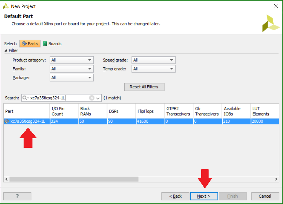
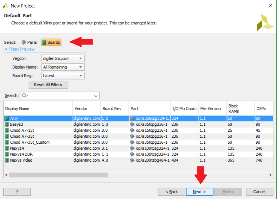
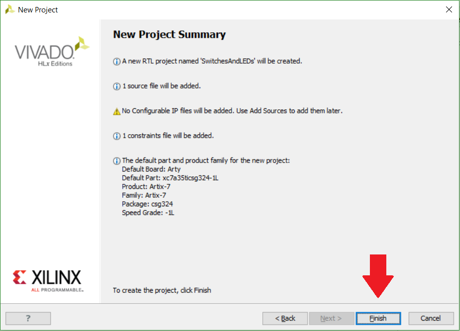
After clicking “Next” after choosing our FPGA board, we will be presented with a final confirmation screen of our new project that we’re about to create. If you’re happy with the summary, go ahead and choose “Finish”.
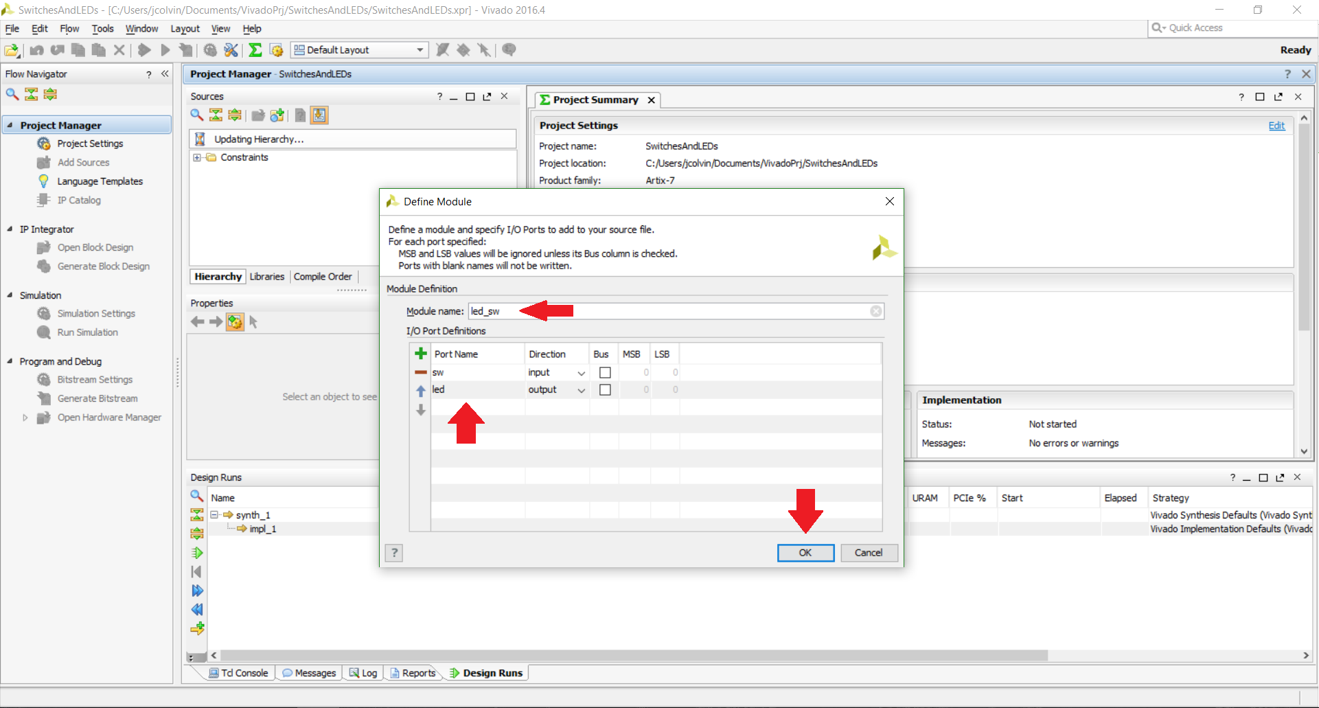
Let’s go ahead and modify our new project. The first window we will encounter is a wizard that lets us configure a new module; this is a part of a Verilog project where we can define the inputs and outputs for our project that we are creating. For this tutorial, we are only assigning an LED to a value of a switch, so we only need to create a single input and a single output (leaving the “Bus” box unchecked for both of them). I named my input and output “sw” and “led”, respectively, although you can name whatever you would prefer. You can also rename your module (if you kept the top.v suggestion as the file name from before, your module will currently be called “top”) to something a little more intuitive if you so desire.
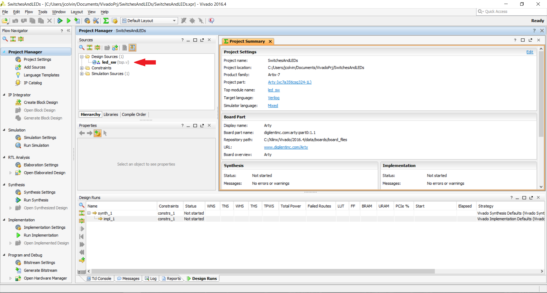
Finally, we’re at the main Vivado GUI where we can actually “do stuff”, i.e., add the code to our Verilog module that tells Vivado what the module is supposed to do, change the XDC file to inform Vivado what physical pins you intend to use with your module, add IP if you choose to do so, and more. Let’s go ahead and add in the Verilog code for our top module.
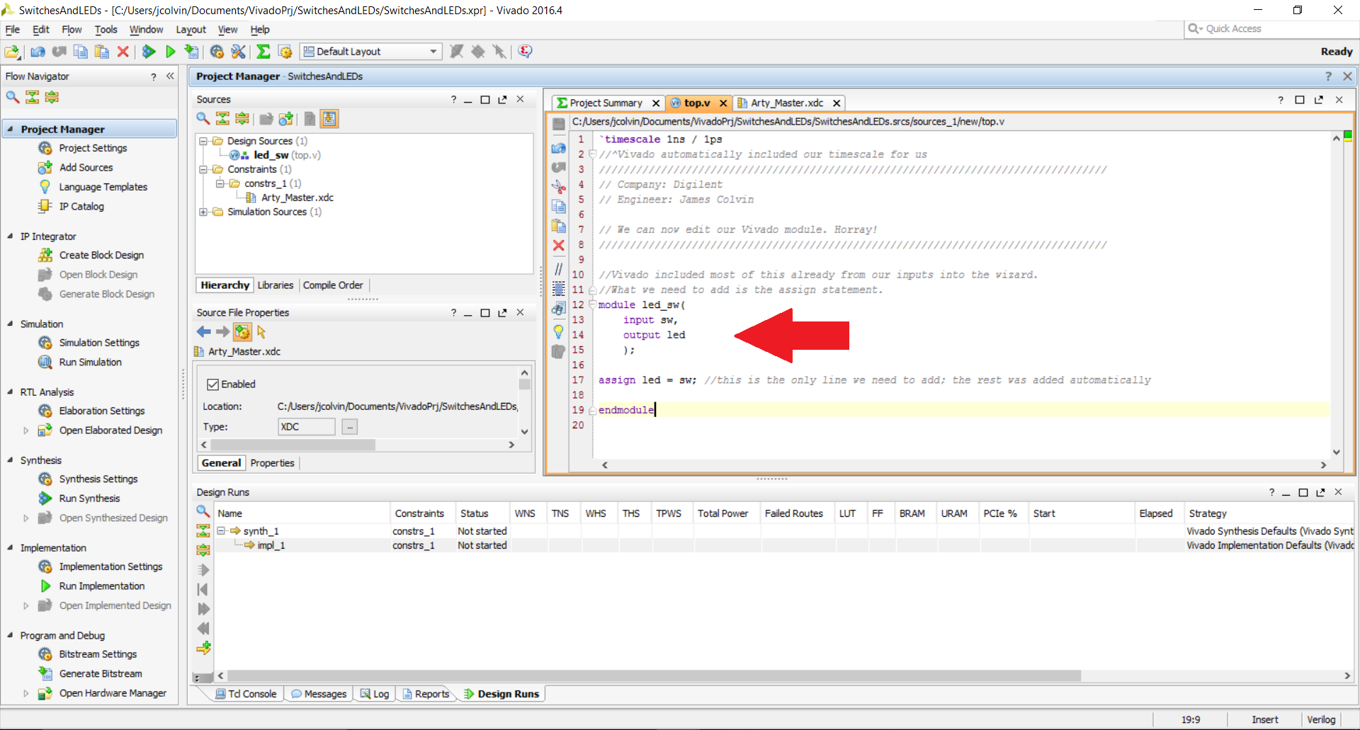
What we intend to do for this particular tutorial is have the state of the LED be dependent upon the state of the associated switch. The keyword that will best model this behavior in Verilog is assign. Double-click on the top module code in the Sources window in the Design Sources folder to have it open up in the editor in the upper right-hand side of the GUI. The line of code that we will want to add is
assign led = sw;
It will go between the closing curly brace and semicolon surrounding the named module that we just created in the wizard. That’ll be all we need to do in the Verilog Module for this project.
The XDC file will require a little more manipulation and is the focal point of what makes FPGAs so versatile to the end user; when this file is edited, we are, in essence, informing Vivado where all of our inputs and outputs on our “black box” are physically located on the FPGA. Vivado does all the heavy lifting in terms of how to actually connect point A to point B using the HDL we created in the Verilog module, while we just have to worry about some external aesthetics. Naturally, this analogy falls short once you get into more complex designs, but it’s fun to think that way. But back to the XDC file itself; how do we actually edit it?
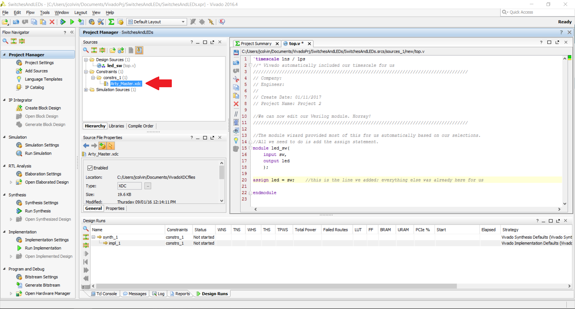
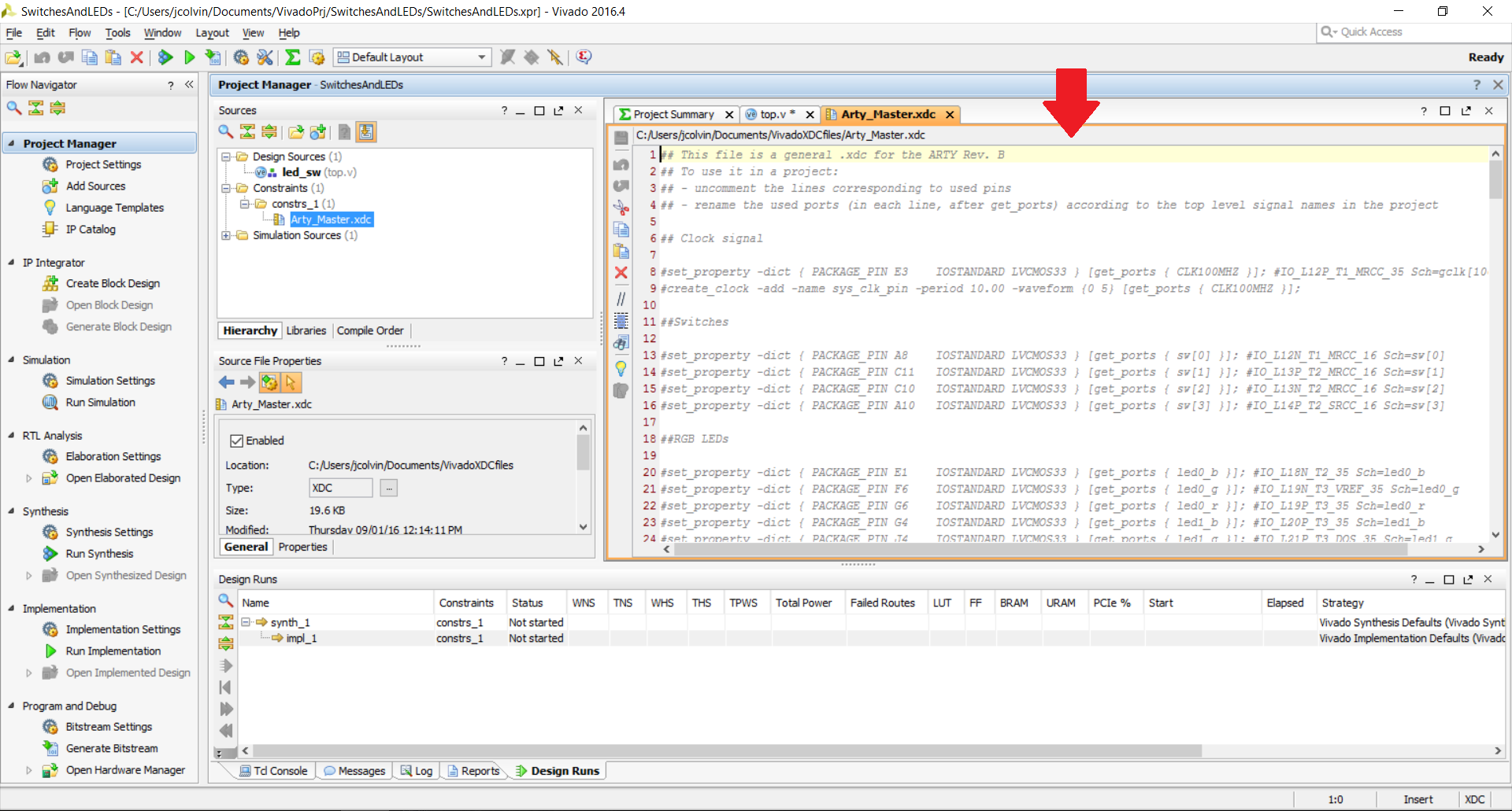
You can find the XDC file in the upper left corner in the Sources window in the Constraints folder. Double-clicking on it will bring up the XDC file in the upper right-hand side of the Vivado GUI. If you are using a master XDC file for a Digilent board, you will notice that everything in the XDC file is currently commented out with a # sign so that Vivado does not interpret it as code to be used. What we will want to do with this project (having the state of an LED be assigned to the state of a switch) is enable our LED and switch of choice.
It’s important to note here that we can’t just use any pin for our LED and switch, despite how I described the XDC file in the previous paragraph. As I am looking to use one of the embedded switches and LEDs already present on the Arty (as that is my board of choice), those components are already pre-wired to a pin on the FPGA and can’t be re-routed without making physical modifications to the board. However, if I instead had an external switch and LED, in theory I could then attach those to any pin in the FPGA that I could physically access. While this might not seem all that different from a microcontroller, this really comes into play when you start to create hardware controllers, but you can place as many as you want wherever you need to rather than being limited to whatever that microcontroller has built into it.
The Digilent master XDC files are organized by physical group on the FPGA, such as switches, Pmod Headers, Ethernet PHY, and the like. For this tutorial project, we can scroll down to the switches and LEDs section and uncomment a single line from both of them by removing the # sign from the front of the associated line of code. Then, we need to edit the name of the pin (between the curly braces immediately following the get_ports statement) to match whatever we called it in our Verilog module.
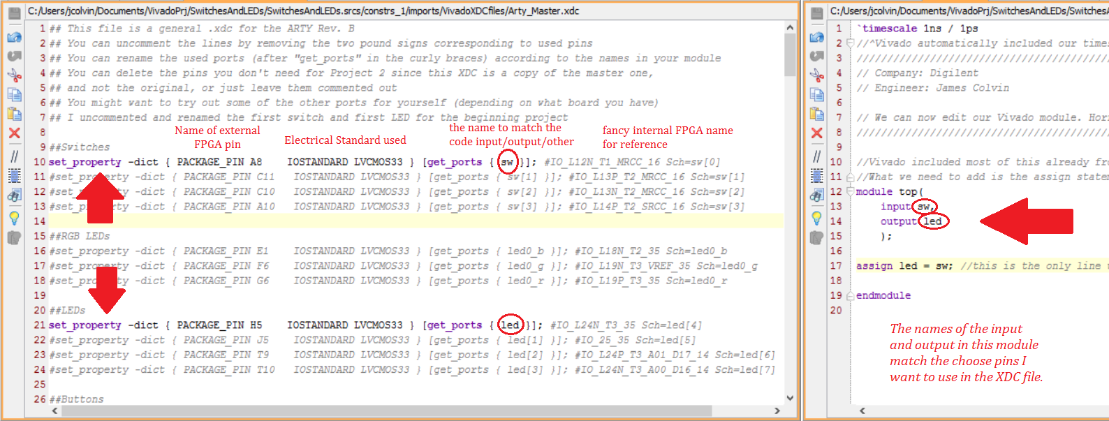
Phew! The Verilog module and XDC file are edited and ready to go! After saving this project, we’ll then be able to generate our bitstream and program the FPGA.
Let’s go ahead and generate the bitstream! In practice, you would be able to simply click on the “Generate Bitstream” button on the left-hand side of the GUI under the “Program and Debug” subsection, but we’ll manually walk through each of the required preceding steps. Presuming your Verilog module and XDC file are already edited to your taste and are saved, go ahead and click on “Run Synthesis” under the “Synthesis” subsection on the left-hand side of the GUI.
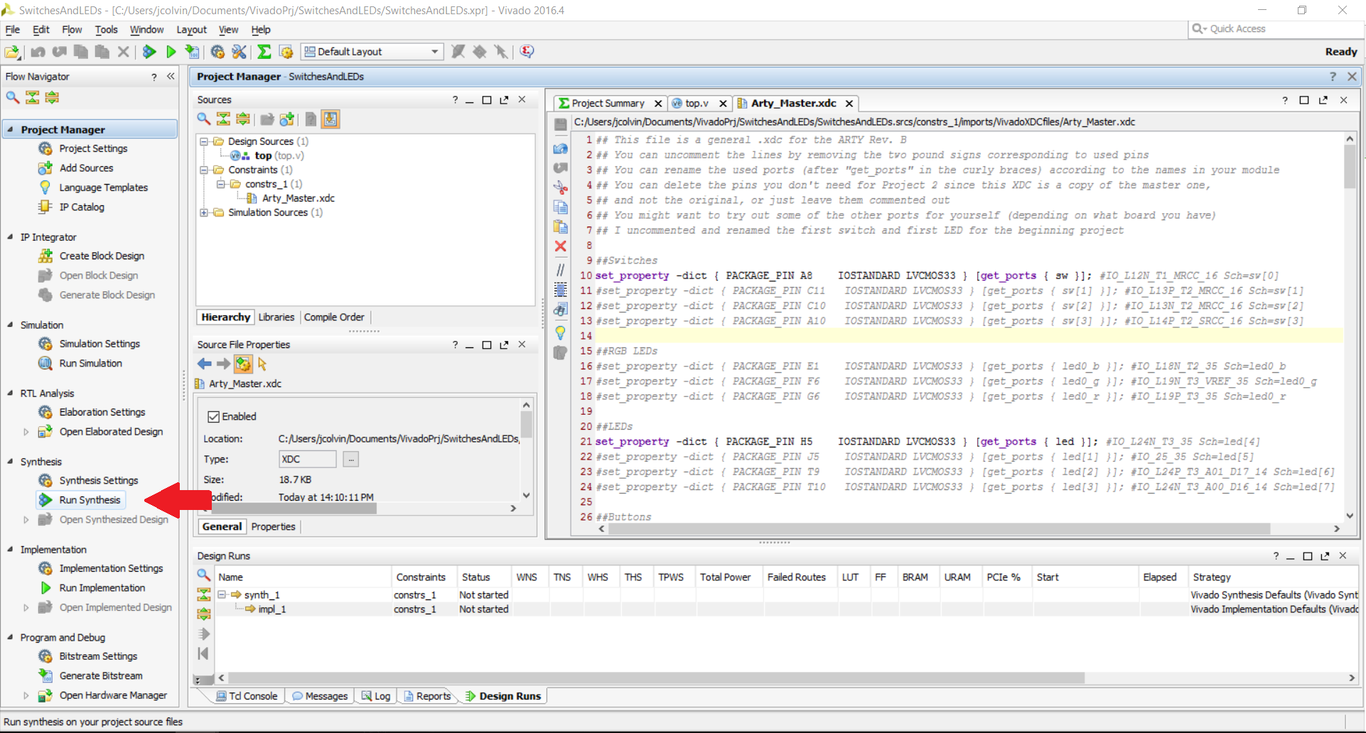
The first time running synthesis (and later times as well if you don’t check the “Don’t show this dialog again” box), you’ll be presented with a wizard showing you some synthesis options. What we want to do is leave our “Launch directory” in the “Default Launch Directory” folder and to choose to have the launch run on the local host (your computer) rather than only generating the scripts. You’ll also be given a dropdown option to choose the “Number of jobs” that Vivado can use; this is essentially the number of computer cores that Vivado is allowed to use on your computer. I recommend choosing the maximum number that is available to you, as getting a bitstream ready to program an FPGA is very computer-intensive. As a side note, the whole combination of synthesis, implementation, and the generation of the bitstream can take quite a bit of time (more than 10 minutes in some cases) since Vivado processes a ton of things hidden to the user and works with the entire FPGA and not just what we are physically utilizing. Click OK after you’re happy with your selections and wait for the synthesis process to complete, which may take a couple of minutes depending on your computer.
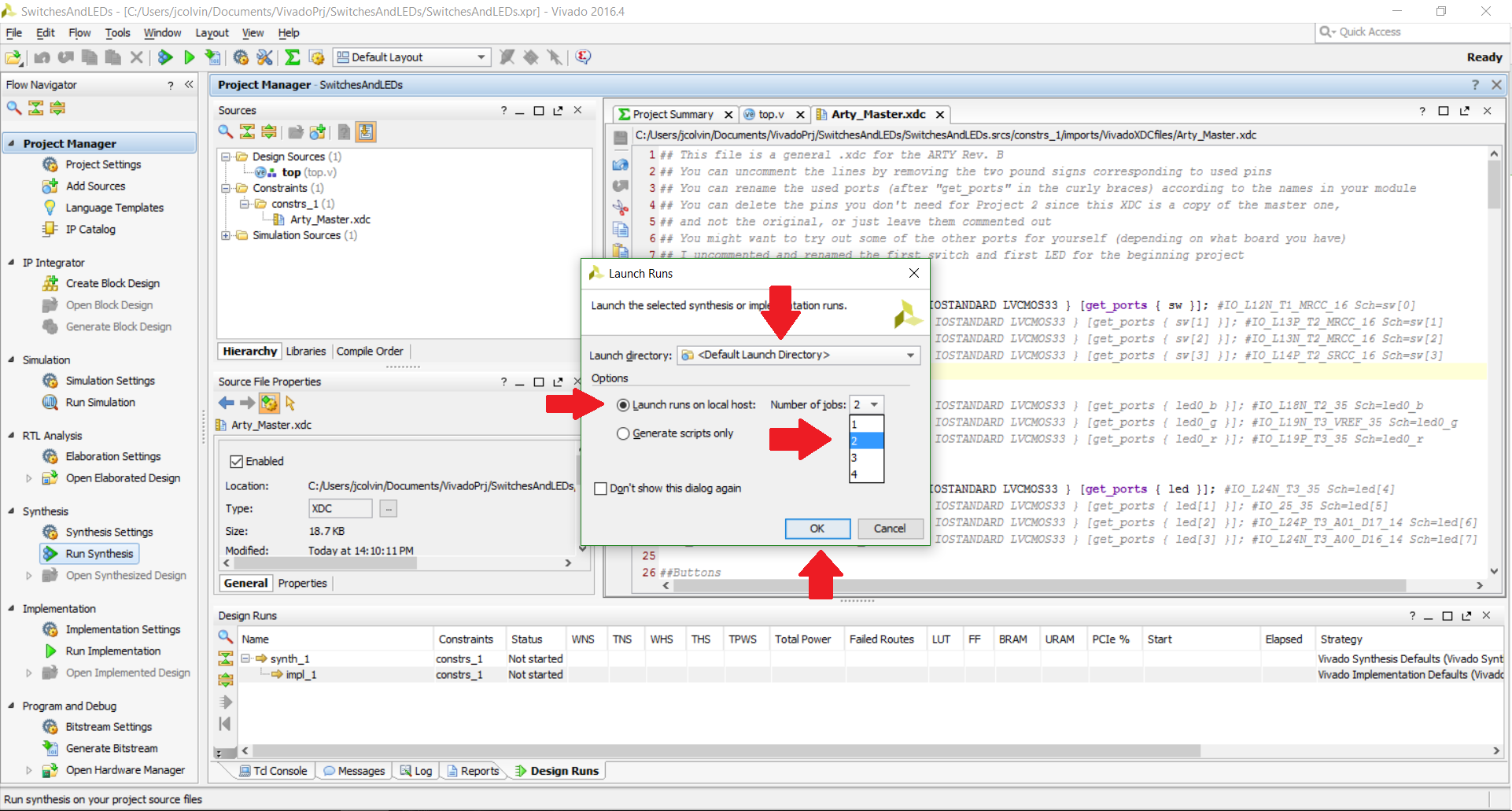
Once it’s done, you’ll then be presented with a pop-up asking you what you would like to do next. Go ahead and choose the “Run Implementation” option. You’ll then see a similar wizard for the implementation process, where you’ll want to keep the default options, but have the maximum number of cores (jobs) be used. This process also can take a couple of minutes.
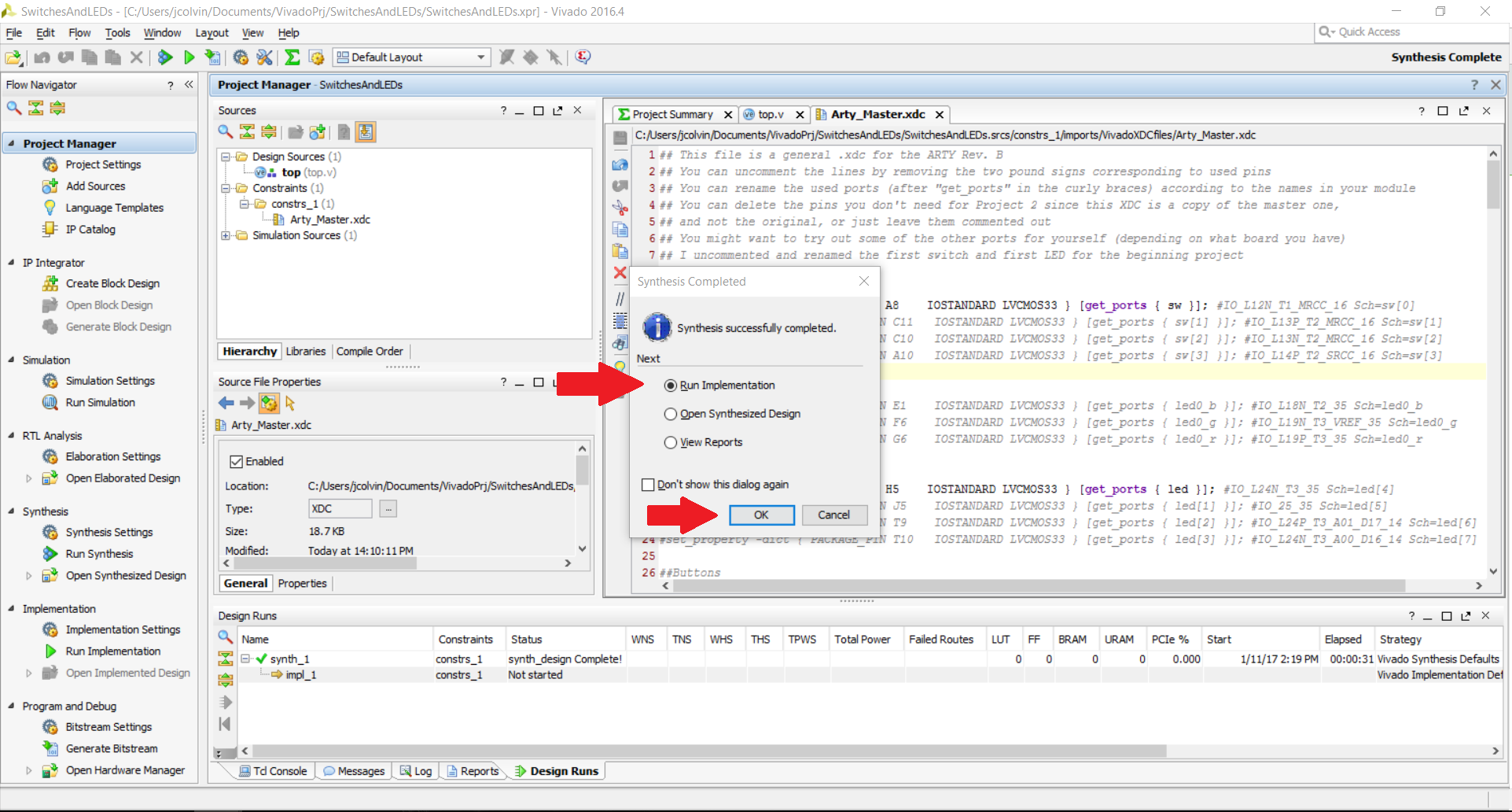
You’ll receive a second popup asking what you want to do next. You’ll want to choose “Generate Bitstream”, but as a side note, you may not necessarily want to click on the “don’t show this dialog again” box this time because if you are designing a circuit for your FPGA to run, you may just want to check to see if Vivado was able to successfully make it through synthesis and implementation. If there is an error, you would not want to generate a faulty bitstream. You’ll then be able to choose some bitstream generation options, much like for synthesis and implementation. When you are happy with your selections, click OK to have Vivado generate the bitstream.
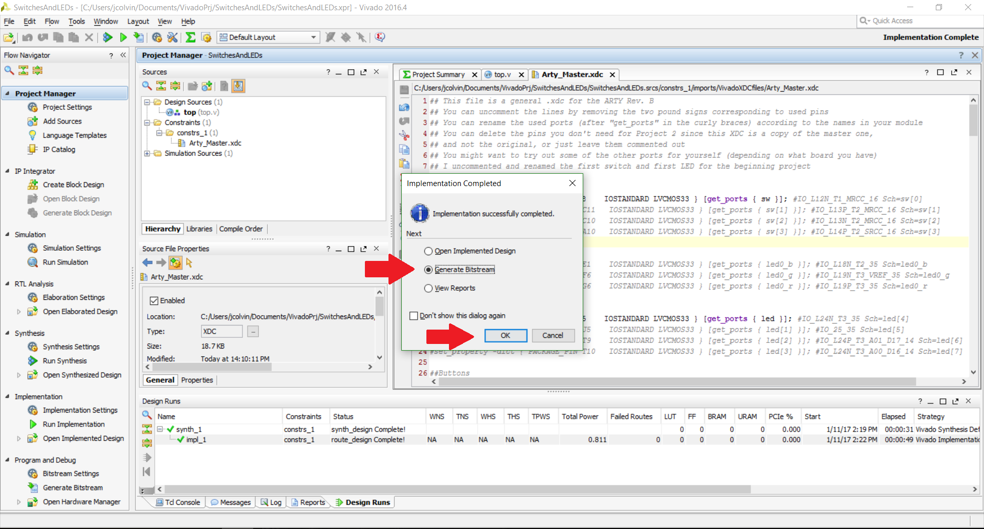
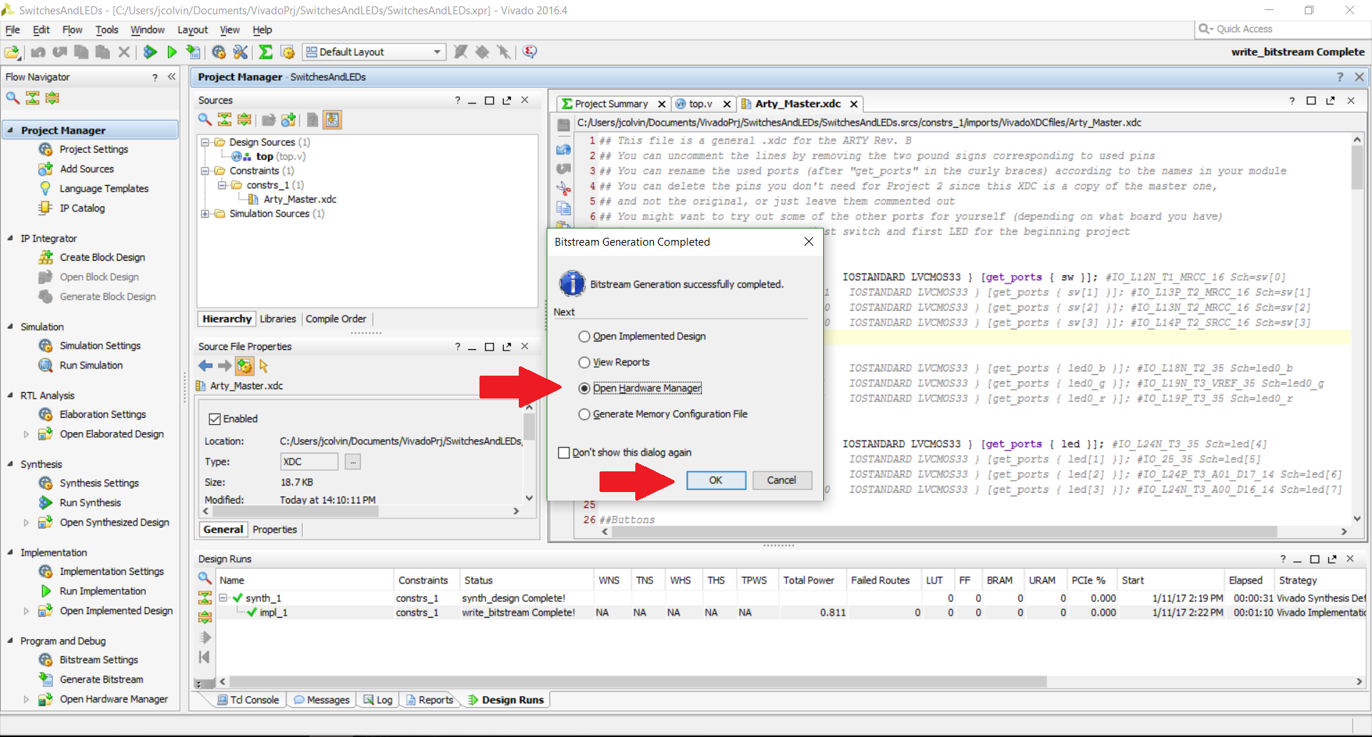
After another few minutes, the bitstream will finally be generated, and all we have left to do is program our FPGA with it! You’ll see another helpful popup where we will get the option to choose to open the Hardware Manager, which is where we will be able to make sure Vivado is connected to our FPGA.
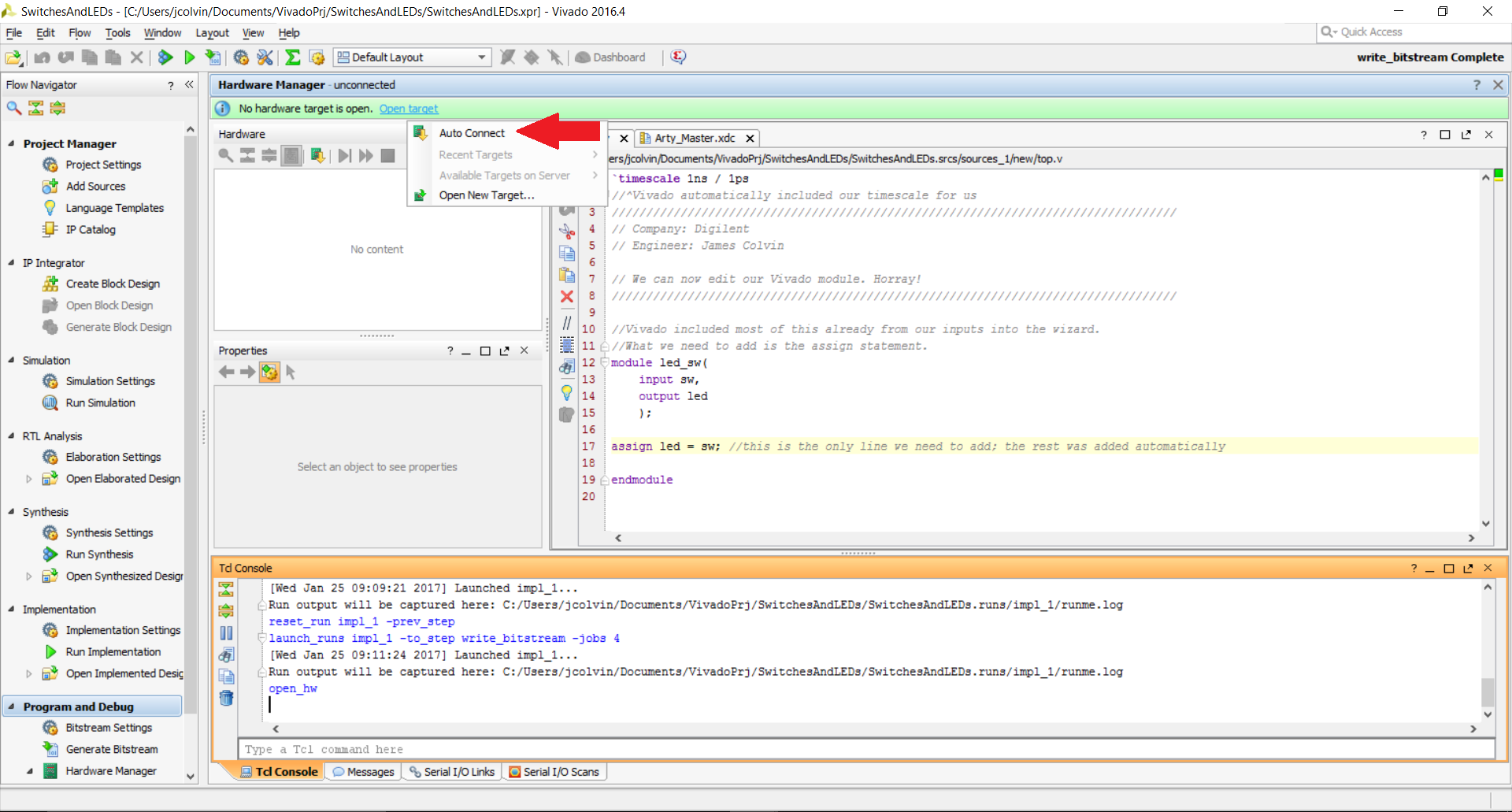
If your FPGA is not connected to your computer already (or if it’s connecting for the first time) you’ll see a green bar at the top that indicates that no hardware target (FPGA) is currently open. After you connect your FPGA to your computer, typically via a micro USB cable, and confirm that the LED power indicator lights turn on, go ahead and click on the “Open Target” button in the green bar and then choose “Auto Connect”.
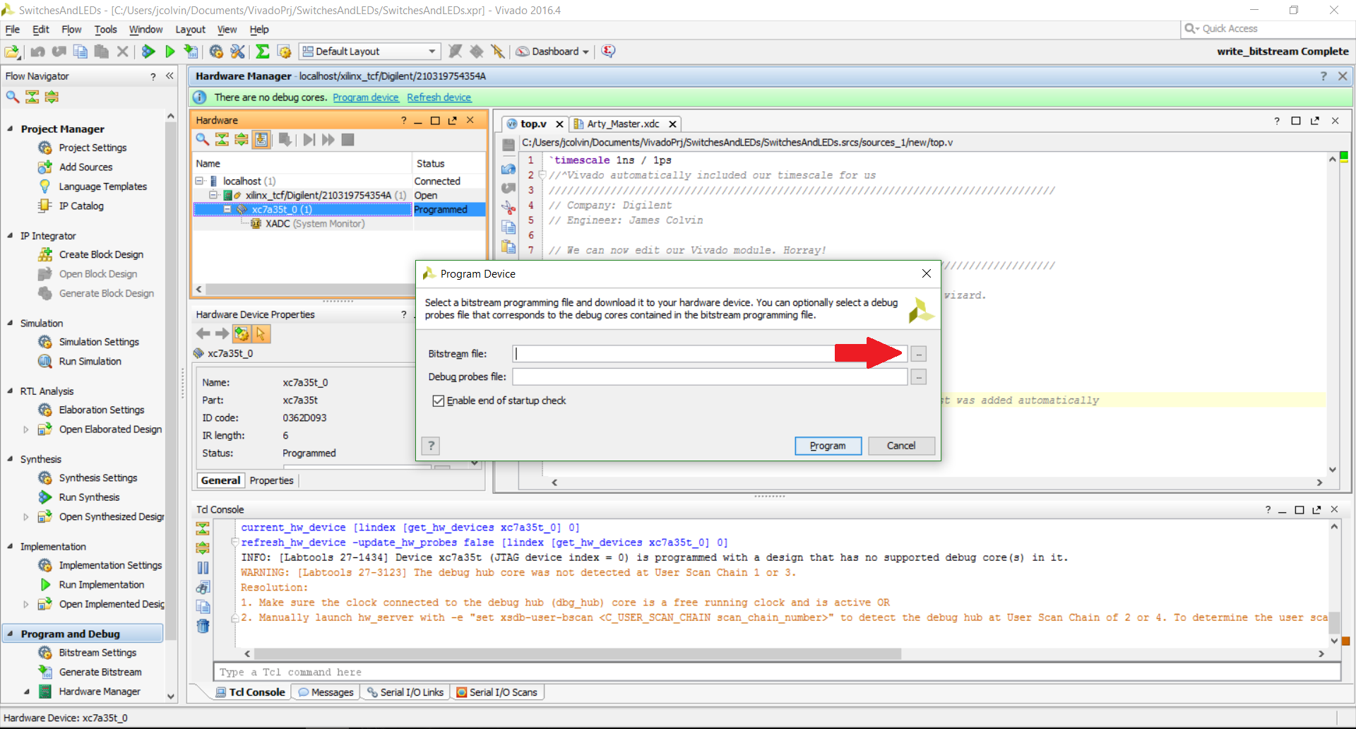
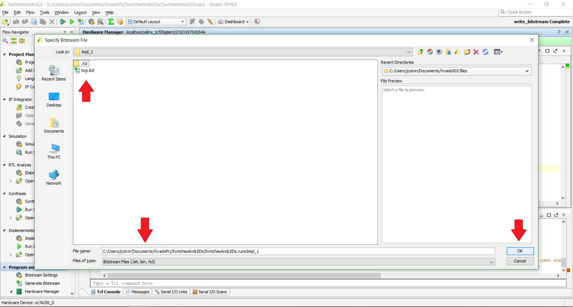
We’ll then be asked to choose the bitstream file to load the FPGA with (we don’t have to worry about the debug probes since we don’t have any in this project). The bitstream file is a little non-intuitive to find; You can find it in your project directory under yourProjectName.runs, then impl_1. Select the .bit file inside that folder, and then choose the .bit file that you see. In this tutorial, the Verilog module is named top, so the bitstream is called top.bit. Click OK to confirm your selection of the bitstream and then click “Program” (you can leave the “Enable end of startup check” either enabled or disabled). Luckily, the programming process itself will take under 10 seconds, so that’s a nice change of pace. (Arty Programming Guide keeps going, into the reference for Arty programming.)
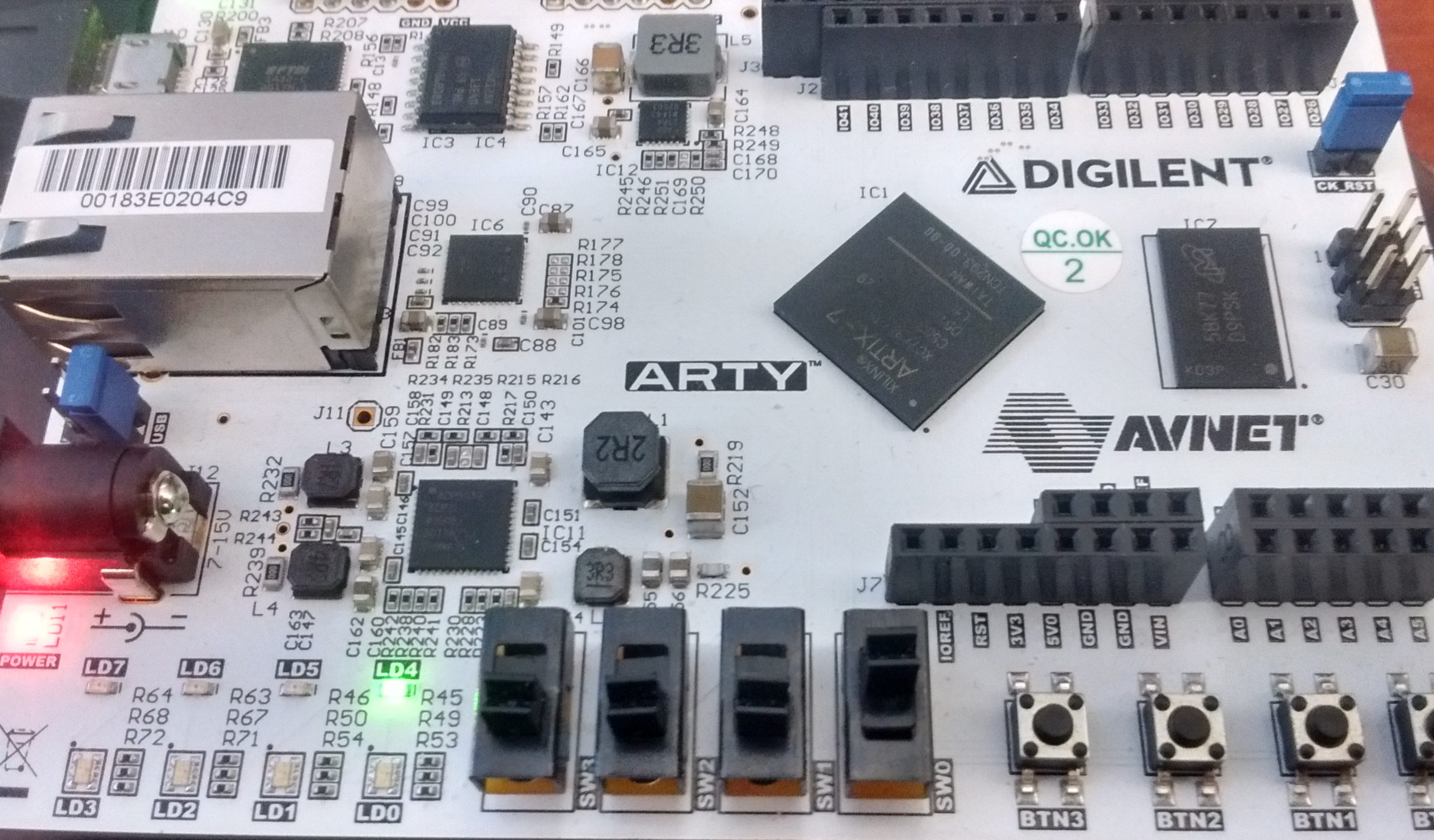
And we’re finally done! The way I set up this tutorial (and my XDC file), I have the first switch (SW0 on the silkscreen) on the Arty controlling the state of the first monocolored LED (LD4), as evidenced in the picture below.
I hope you all enjoyed this tutorial!
Please feel free to comment with any questions you have or any other tutorials you would like to see in the future! Additionally, check out our Wiki for more resources on this project.


can I ask you about bit file? how u can create the bit file? I just started about matlab. thanks
Hello,
Xilinx’s Vivado Design Suite is what creates the bit file. None of us here at Digilent have really worked with MATLAB so we don’t have a ton of advice available for you in that regard. MATLAB does have a nice introduction page that includes some videos on this available on their website here here.
If you have any further questions about this, please post your question on our technical forum, https://forum.blog.digilentinc.com/, where one of the Digilent engineers will be able to see and respond to your question.
Thanks,
James Colvin
Can you suggest any way to run Matlab code in vivado
Vivado itself doesn’t run MatLab code, but we have another post that maybe be of interest to you HERE. This page on MathWorks’ website might be a good one for you as well.
Hi do you think you can create a bitstream for the ravencoin kawpow miner/algorithm?