

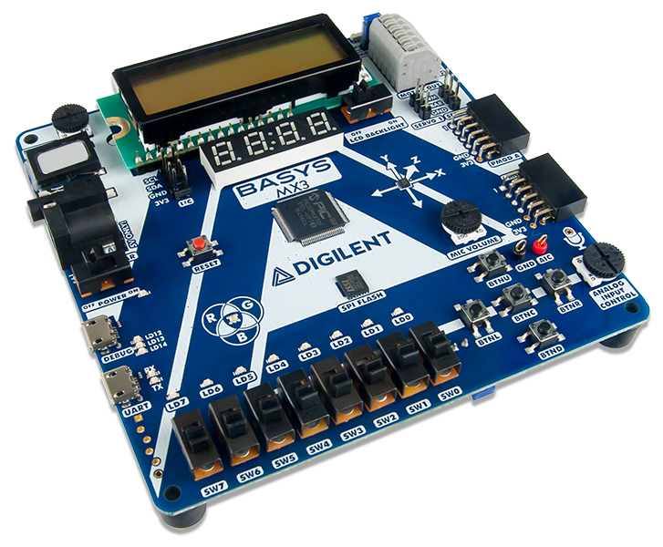
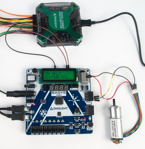
 We recently announced our newest microcontroller board, the Basys MX3. This board was designed specifically for use in teaching Embedded Systems and related courses. Although it has many great features, such as an exhaustive set of peripherals, special (and really cool looking) silkscreen to maximize readability, and an Analog Discovery 2 connector for investigating signals, the most exciting feature for me is the in depth coursework that comes with it. This coursework, titled “Embedded Systems with the Basys MX3 and PIC32MX370,” is completely free, open-source, and completes a full walkaround of the board. It also uses the free and professional grade toolset, MPLAB X. With a total of 7 theoretical teaching units and 15 labs, “Embedded Systems with the Basys MX3 and PIC32MX370” is meaty enough to teach one to two semesters of embedded systems related courses. Below you’ll find a breakdown of the coursework and the concepts and skills each unit/lab targets.
You can find all units and labs on the Basys MX3 Resource Center. Solutions to the labs are available to instructors upon request.
Right from the get go students start getting familiar with the PIC32MX370 hardware by programming registers and creating a hardware configuration file. Data flow and control flow diagrams are used as part of project planning and to teach best design practices, including when and how to test. If students aren’t familiar with the MPLAB X software or need to brush up on programming in C, links to various tutorials are included. Some key takeaways for the students are:
-
Understand best practices for creating dependable and sustainable software.
-
Know how to generate a microprocessor development project using MPLAB X.
-
Know how to generate a config_bits file for the PIC32MX370 processor.
-
Know how to configure the Microchip PIC32 processor pins as either digital inputs or outputs.
-
Understand the drive capability of a processor digital output.
-
Know how to write a C program for a specific application using an embedded system.
-
Know how to make speed performance measure on a processor-based system.
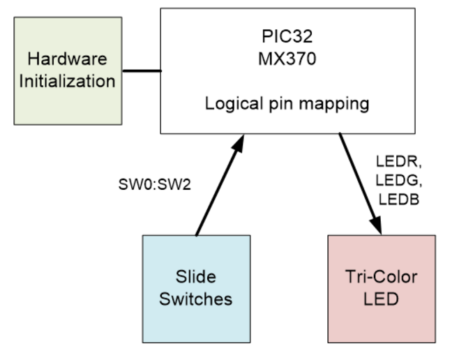
The concepts discussed in Unit 1 are put into practice here by requiring the students to write a program that uses the onboard switches to control the onboard RGB LED according to specified design requirements. Students become familiar with read-modify-write operations to control the PIC32MX370 registers.
The skills acquired in Lab 1a are extended to require students to create a simple calculator using the onboard switches, buttons and seven segment display (SSD). Students are introduced to timing through the use of software delay to achieve persistence of vision on the SSD, as well as atomic bit manipulation and bit-banging techniques.
Unit 2 Elements of Real-time Systems
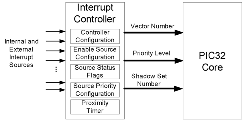
Through the classic example application of controlling the rotor speed of a stepper motor, this unit investigates the concepts of multi-threaded process time management for a real-time dynamic system, using foreground-background task scheduling. Counter/timer hardware is discussed in some detail. Some of the key takeaways are:
-
How to implement task management based on polling PIC32 timers.
-
How to implement task management based on PIC32 timer interrupts.
-
How to set the period of a PIC32 timer.
-
How to write a software state machine.
-
How to allocate tasks to either foreground or background scheduling.
-
Understanding of stepper motor operations and applications.
Adapting the code previously used in Lab 1a and 1b, students are required to display the state of the onboard push buttons on the onboard LEDs using debouncing techniques, change notification interrupts and polling.
Extending the skills acquired in Lab 2a, students are required to control the mode and direction of a stepper motor using the push buttons, control the speed of the stepper motor using the slide switches, and display the speed of the motor on the SSD.
Unit 3 Parallel IO and Handshaking for LCD Control
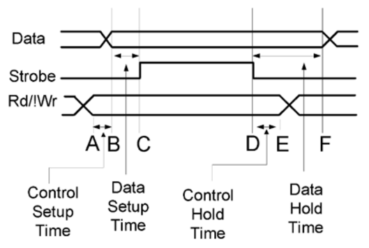
In Unit 3, students are introduced to digital communication through displaying static and dynamic data on the onboard parallel LCD. Students will learn to translate timing diagrams provided by target equipment data sheets into timed sequences of program instructions, how to use ASCII encoded data, as well as experiment with the mechanisms required to synchronize asynchronous systems using hardware and software handshaking. Some of the key takeaways are:
-
How to use control flow diagrams to generate program code.
- How to implement a bi-directional parallel IO interface.
-
How to use software delay to write control commands at specified intervals.
-
How to use software code to generate minimum setup and hold times.
-
How to implement one form of handshaking.
-
How to read and interpret timing software modeling diagrams.
Using direct IO control through bit-banging, students will develop and test a library of functions that allow text to be placed at any position on the onboard parallel I/O character LCD, following the data flow and control flow diagram models presented in Unit 3.
Using IO control through the parallel master port (PMP), students will develop and test a library of functions that allow text to be placed at any position on the onboard parallel I/O character LCD, following the data flow and control flow diagram models presented in Unit 3.
Unit 4 Communications – Synchronous and Asynchronous Serial Protocols
Unit 4 consists two parts. Part 1 contains an overview that addresses different high level views of digital communications including synchronous vs asynchronous and networking. Part 2 further addresses asynchronous communications protocols, specifically the Universal Asynchronous Receiver Transmitter (UART) protocol. Some key takeaways from Part 1 and Part 2 combined are:
-
Understanding of the basics of telecommunications.
-
Understanding of requirements and implementations of asynchronous and synchronous communications.
-
Application of asynchronous communications.
-
Knowledge of a PC terminal emulation program.
-
How to develop a library of PIC32 software to provide bi-directional communications of single characters and strings of characters.
-
How to use the UART for diagnostics and as a human-machine interface (HMI).
-
-
How to recognize the handshaking methods used in a communications protocol.
-
How to set up the Analog Discovery 2 to display communication signal waveforms.
Students will call on their experience with controlling a stepper motor from Lab 2a, only this time the motor will be controlled from a PC terminal via UART. Serial communications will be displayed on both the PC terminal using a terminal emulation program and the LCD onboard the Basys MX3.
Lab 4b requires all of the elements of software code developed and hardware used in previous labs. Students will extend the knowledge gained in Lab 4a by specifying a system that is capable of two independent control and monitoring locations, which is common to many industrial applications.
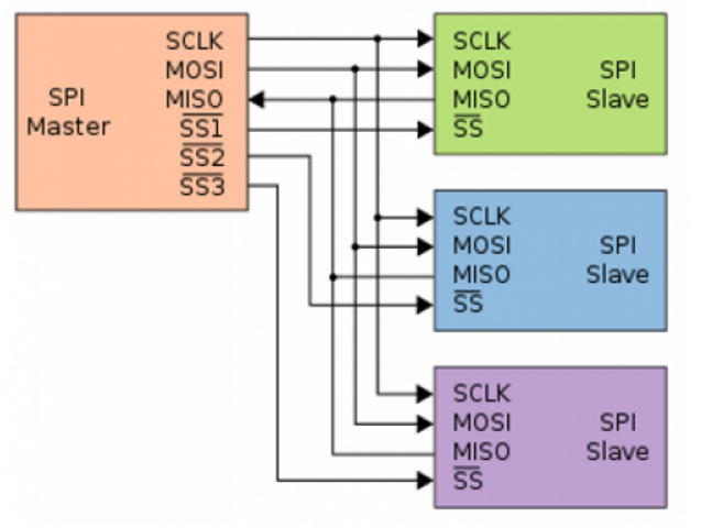
Students develop a software system that allows the PIC32MX370 to write an arbitrary number of 8-bit bytes to an arbitrary address location in the SPI flash memory device. The stored data must also be read back to determine if the data read matches the data written.
Using I2C communications, the student will program the PIC32MX370 processor to periodically read the physical orientation data from the onboard 3-Axis accelerometer and display the information on a character LCD and send a text stream to a computer terminal.
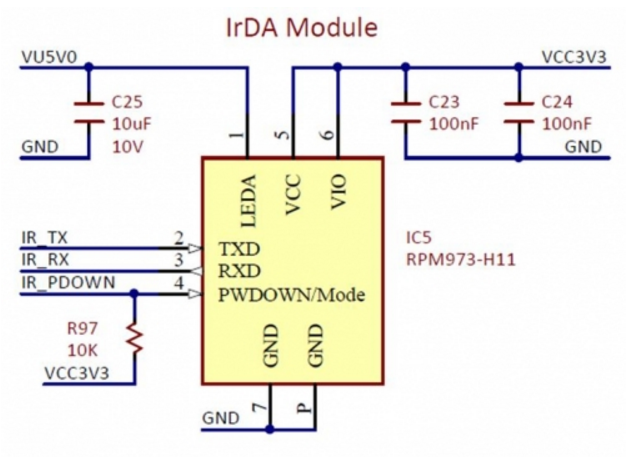
Unit 5 IrDA Communications Protocols
This unit demonstrates how to use interrupts and the core timer to decode two IrDA protocols, in an effort to teach approaches for decoding different IrDA protocols used for remote device control. The IrDA is the only implementation of wireless communications included in this coursework, as well as the only unit requiring the use of an the Analog Discovery 2 (or similar instrument). Some of the key takeaways are:
- Understanding of the basics of IrDA protocols.
- Using instrumentation to characterize data streams.
-
Use processor external interrupts to decode signal timing patterns.
-
Approaches to using state machines to process data.
The format of this lab differs from the rest in this series in that the hardware is not entirely specified. The student is intended to use an IR remote control device of his or her own choosing and to analyze the IrDA signal to generate an application that can exchange IrDA messages with that device.
Unit 6 Analog IO and Process Control
Unit 6 introduces students to working with analog signals. The purpose of this unit is to investigate applications of embedded controllers to real time control algorithms that employ analog inputs and analog outputs. Students will use a computer algorithm to implement a closed-loop processor for motor speed control, and see how feedback can be used to linearize an inherently nonlinear process and result in zero steady state control error. Some of the key takeaways are:
-
How to read analog voltage with a PIC32 processor.
-
How to use the PIC32 Output Compare to implement a PWM analog output.
-
How to use the PIC32 Input Capture period measurement to implement a tachometer.
-
The advantages of using period measurements as opposed to frequency measurements and vice versa.
-
Fundamental digital filtering concepts for data smoothing.
-
Open-loop and closed-loop process control.
This lab focuses on open-loop control. Students will use the potentiometer labeled Analog Control Input onboard the Basys MX3 to set the percent PWM to operate the speed of the motor from 0 rpm to the maximum the motor can achieve given the motor performance and the supply voltage.
Building upon Lab 6a, Lab 6b introduces closed-loop control by implementing a digital PI controller. The tachometer frequency will be measured by using the Input Capture of the PIC32 to determine the signal period which is then inverted to yield the frequency.
This unit focuses on processing signals in the audio frequency range using digital signal processing (DSP) concepts with the PIC32MX370 microprocessor. Both a method of generating multiple frequency signals without using transcendental functions or lookup tables, and Discrete Fourier Transforms (DFT) to detect the presence of signals will be used. It is not the purpose of this unit to teach the theory of digital filtering, but rather to teach how to implement digital filtering using a conventional microprocessor in lieu of specialized digital signal processors. Some of the key takeaways are:
-
How to implement digital filters in C using a PIC32 microprocessor.
-
How to create analog output using pulse-width modulation.
-
How to sample an analog input at a specified rate.
-
How to use the PIC32 processor to make a signal generator.
-
How to use the PIC32 processor to make a real-time frequency spectrum analyzer.
This lab requires much of the code written for previously labs and adds use of the onboard speaker and microphone. Students are to create a digital sine wave generator capable of synthesizing eight constant amplitude signals at specified frequencies. The frequency of the sine waves will be selected by setting one of the eight slide switches. The audible output will be enabled and the frequency displayed on the 4-digit 7-segment display for five seconds when BTND is pressed. The LCD will display the frequency of the selected sine wave.
Adding to Lab 7a, the lab series culminates in the students creating a spectrum analyzer using the Discrete Fourier Transform. Students will experience how use of the Fast Fourier Transform and MIPS DSP library greatly reduces execution time.
All Units and Labs for “Embedded Systems with PIC32MX370 and Basys MX3” can be found on the Digilent Wiki both in Wiki format and PDF. For any questions regarding use of the material, please feel free to comment below or reach out on the Digilent Forum!
It is nothing but the overview of any kind of embedded systems is such a platform where the hardware and the software are combined to produce a better platform as well. It is suggesting all the embedded tools that have the better capability to provide all kind necessary fruitful features.
Running MPLAB 5.05 and I get frequent notices the “Connection Failed” after compiling. I’ve found that I must power down board, wait awhile and power up again before trying again. Even tthen I will get another connection failure. Any hints?