

 Announcing the addition of the Pmod VGA to Digilent’s Pmod line!
Description
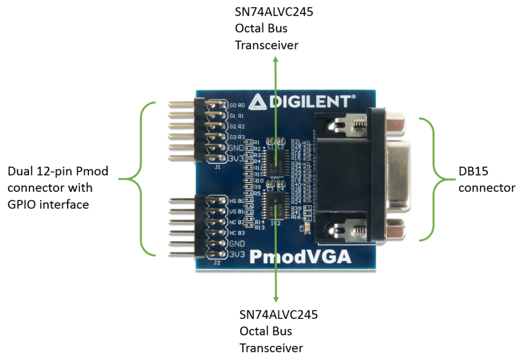
The Pmod VGA uses 14 input pins to create an analog VGA output port. This translates to 12-bit color depth and two standard sync signals: Horizontal Sync (HS) and Vertical Sync (VS). The digital-to-analog conversion is done using a simple R-2R resistor ladder. The ladder works in conjunction with the 75-ohm termination resistance of the VGA display to create 16 analog signal levels for the red, blue, and green VGA signals. This circuit produces video color signals that proceed in equal increments between 0 V (fully off) and 0.7 V (fully on). With 4 bits each for red, blue, and green, 4096 (16x16x16) different colors can be displayed, one for each unique 12-bit pattern.
When used with an FPGA host board, a video controller circuit must be created in programmable logic to drive the sync and color signals with the correct timing in order to produce a working display system. It may be possible to drive the video signals using a very fast microcontroller with a parallel bus controller, however, Digilent does not provide examples for this use case.
How does it work?
The Pmod VGA itself really only has two tasks: convert the digital red, green and blue signals coming from the FPGA board to analog, and pass through the HS and VS timing signals. The more interesting piece is the VGA controller itself.
What is a VGA controller?
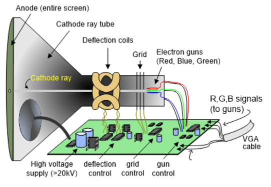
Modern VGA displays can accommodate different resolutions. Using the horizontal-sync (HS), vertical-sync (VS) and pixel clock signals, a VGA controller circuit is what dictates the different resolutions. It achieves this by producing timing signals to control the raster patterns. Raster video displays define a number of “rows” that corresponds to the number of horizontal passes the cathode (see below image) makes over the display area, and a number of “columns” that corresponds to an area on each row that is assigned to one “picture element,” or pixel. The overall size of a display and the number of rows and columns determines the size of each pixel, aka the resolution.
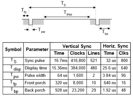
A VGA controller circuit must generate the HS and VS timing signals and coordinate the delivery of video data based on the pixel clock. The VS signal defines the “refresh” frequency of the display. For a 640-pixel by 480-row display using a 25 MHz pixel clock and 60 +/-1 Hz refresh, the signal timings shown below can be derived.
A VGA controller circuit, such as the one pictured below, decodes the output of a horizontal-sync counter driven by the pixel clock to generate HS signal timings. You can use this counter to locate any pixel location on a given row (you can think of it as locating a column). Likewise, the output of a vertical-sync counter that increments with each HS pulse can be used to generate VS signal timings, and you can use this counter to locate any given row. These two continually running counters can be used to form an address into video RAM. No time relationship between the onset of the HS pulse and the onset of the VS pulse is specified, so you can arrange the counters to easily form video RAM addresses, or to minimize decoding logic for sync pulse generation.
For a much more in depth discussion of how VGA displays work, see the Pmod VGA reference manual.
Applications
The Pmod VGA can be used to drive standard displays such as televisions and monitors. It is best suited for use with Digilent FPGA boards as the host board must be capable of driving a fast parallel data bus in order to properly drive a display.
Getting Started with the Pmod VGA
As mentioned above, we do not recommend using the Pmod VGA with any Digilent microcontroller boards. But if using a Digilent FPGA board, we’ve written a VHDL demo project to get you up and running quickly driving a VGA display.
For questions or comments, please visit the Digilent Forum or leave a note in the comment section below!