

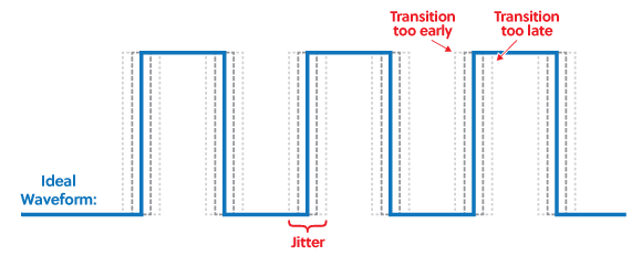
What is jitter?
Jitter is the variance in where exactly a clock falls. You might expect that a 100 MHz clock has edges that occur exactly every 10 ns. However, this can vary, depending on the quality of the clock source, the paths that the clock travels down to get to where it is used, and can change depending on circuitry that modifies the clock to get required frequencies, duty cycles, and phase shifts with respect to other clocks.
Why does this matter?
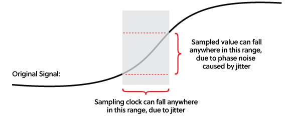
In signal acquisition, clock jitter causes noise. The following diagram shows how the signal being captured and the jitter combine to cause variance in the actual measured value of a sample. This noise is referred to as phase noise because it is caused by variance in the phase of the clock – edges are phase-shifted forward or back as compared to the edges you would see on the ideal clock.
Why does signal noise matter?
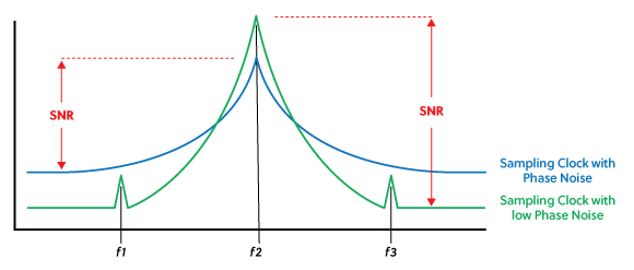
Especially in software-defined radio (SDR), noise in a captured signal can obscure critical components of a signal. In the following diagram, showing the theoretical spectrogram of signals captured with relatively low and high jitter, you can see how components that are obscured when the phase noise is too high appear when a clock source with lower phase noise is used and the signal-to-noise-ratio is improved. The “skirt effect” spreads the poorer capture out over a wider band of frequencies, obscuring smaller signals that may still be of interest. Due to the improved “height” (range) of the low-noise signal, you also get a higher effective resolution.
Why not use clocks generated in the FPGA?
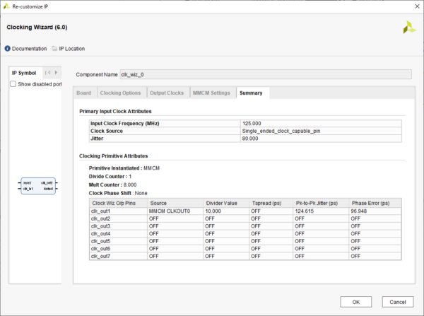
In some applications, you should be using specific clock frequencies in order to capture your signal of interest. If the clock frequency doesn’t match some multiple of the frequency that the signal is being produced at, the phase of the acquisition could drift over time. So, you need to produce a clock of the appropriate frequency by using FPGA resources to modify whatever clock sources you have been provided. However, FPGA PLLs/MMCMs can cause additional jitter to be added to a derived clock. This can be seen in the clocking wizard in Vivado. Here, we can see that, given the settings selected, a 125 MHz input clock producing a 100 MHz output clock increases the jitter of the clock from a specified 80 (ps) to 124.615 ps.
Note: these exact numbers are not necessarily representative of a real design, they are used only to demonstrate the principle of jitter increasing as a clock passes through clock management resources.
So, to revisit the original question, why does the Zmod Digitizer have a low-jitter clock source?
It improves the signal-to-noise ratio and frequency resolution of captured signals, reduces noise, and makes it easier to pick out smaller components that have frequencies close to a much stronger component of an acquired signal. This feature makes it well-suited to SDR applications with potentially stringent requirements.
As someone who is new to the field of signal acquisition, I found this article to be very informative and helpful in understanding the importance of clock jitter and its impact on signal noise. The explanation of the variance in where a clock falls and the effect on phase noise was easy to understand and the diagrams were helpful in visualizing the concepts. I appreciate the focus on software-defined radio and the real-world implications of capturing a signal with too much noise. Overall, this article has piqued my interest in learning more about the Zmod Digitizer and the importance of low-jitter clock sources in signal acquisition. Thank you for sharing this informative piece!