

A common point of confusion that I see both at events and among forums on the internet, is that the Electronics Explorer Board(EE Board) looks just like a big breadboard. Although on first inspection it may look that way, if you turn it around to the back you can see just how much technology is put into this portable workstation.
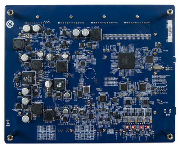
Some of the highlights are 14 bit DACs, and 10 bit ADCs, and connecting it all is a Spartan 3E FPGA.
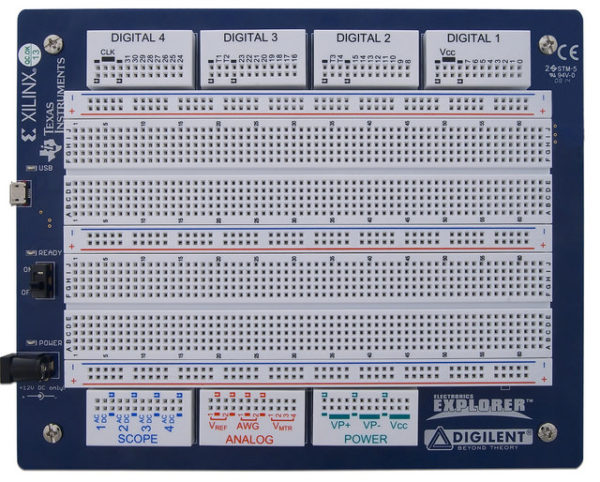
So now that we know that it isn’t just a breadboard, lets get into what it really is. First let’s take a look at the hardware.
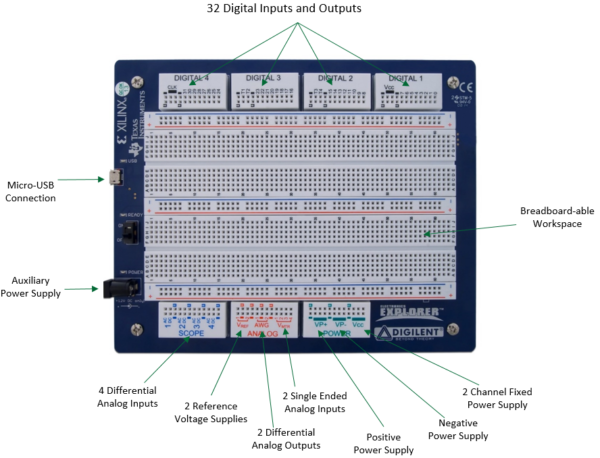 Starting on the top left of the board we see the Micro-USB connector that is used to provide communication between the hardware, and the Windows, Mac or Linux run software.
The auxiliary power supply is required to power the board and all of the tools. Along the bottom we have the Scope, Analog and Power sections of the board.
The SCOPE section consists of 4 differential analog inputs, with a DC and AC channel on each one. The ANALOG section consists of 2 reference voltage supplies, 2 differential analog outputs, and the 4 voltmeter channels.
The POWER section contains VP+, the positive power supply, vp- the negative power supply, and Vcc the 2 channel fixed power supply.
On top you have 32 digital inputs and outputs. And of course in the middle is the large breadboard-able workspace.
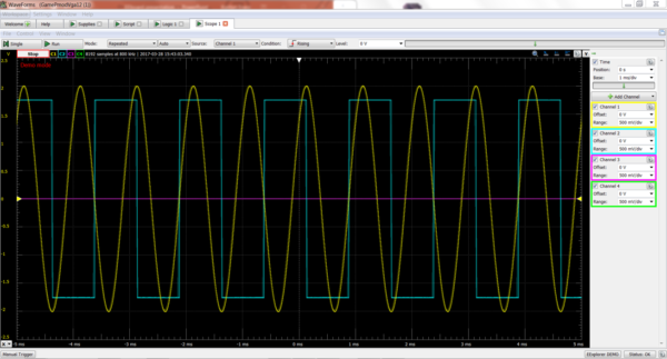
These inputs and outputs were all designed for use with specific tools. All of these tools can be accessed through WaveForms or WaveForms 2015, which is the free, Mac, Linux, and windows compatible software toolset. The EE Board features the same tools as the Analog Discovery 2, but with different specifications, number of channels and for some of them slightly different features.
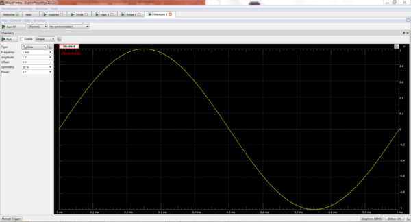
The first tool is an Oscillocope:
There’s also a WaveForm Generator:
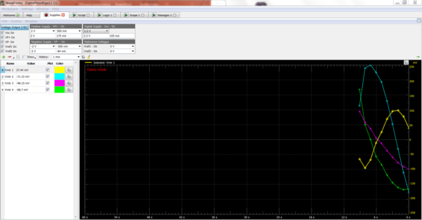
There is a Power Supply tool:
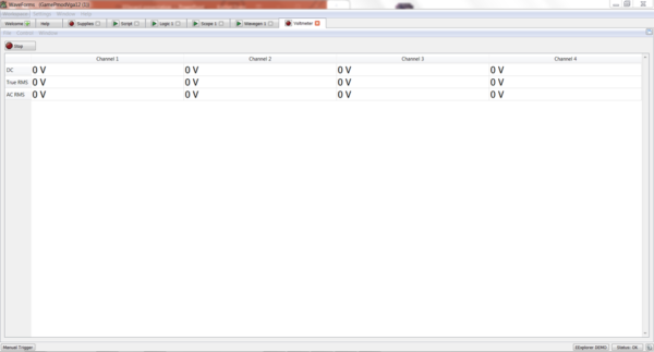
There is a Voltmeter:
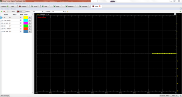
There is a Data Logger:
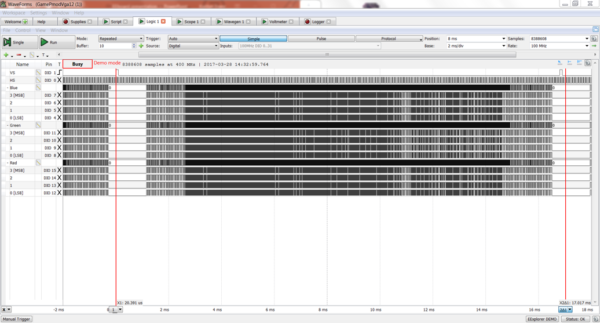
There is a Logic Analyzer:
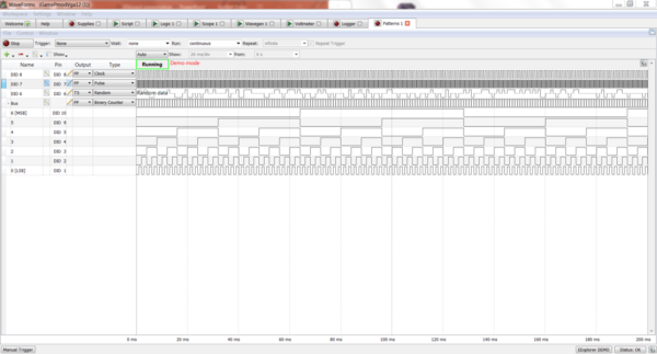
There is also a Pattern Generator:
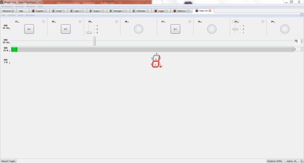
The Digital IO can simulate IO in static IO:
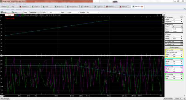
There is a Network Analyzer:
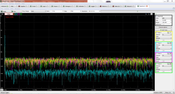
There is a Spectrum Analyzer:
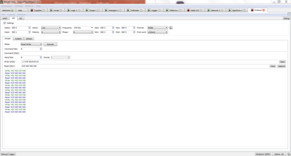
There is a Protocol Analyzer:
Last but not least is the Script Editor. If your application requires the use of multiple tools, any automation, or custom decoding, the script editor will allow you to write Javascript scripts using the pre-exisiting tools.
For more information on the EE Board and to view the Getting Started Guide, check out the board’s resource center. You can see how the EE Board stacks up against other Instrumentation tools here.