

Although this blog post will specifically detail how to use the PmodOLEDrgb with the chipKIT MX3, it will also be very useful for getting the PmodOLEDrgb up and running and communicating via SPI on most of our chipKIT boards. The example provided here will cover how to get set up with the necessary software, how to properly connect the hardware, and how to use some simple library functions to draw shapes on the display.
And it happens to be a great time to try this out during our Pmod Summer Sale!
The PmodOLEDrgb is a 19.99$ RGB organic LED display that plugs nicely into any Pmod host port. Pmod host ports can be found on three different chipKIT boards. They are the chipKIT MX3, chipKIT Pro MX4 and chipKIT Pro MX7. Additionally, the chipKIT Pmod Shield can be used with the chipKIT uC32 and chipKIT WF32 to conveniently add Pmod host ports. If your board is either the chipKIT Max32 or the chipKIT Wi-FIRE then some extra wires will be needed. All chipKIT boards feature a 32-bit PIC32 microcontroller from the Microchip PIC32MX or PIC32MZ microcontroller families.
Software and Libraries
You will need MPIDE downloaded in order to follow this example; you can get that here. We also have an Instructable (Uploading Code with MPIDE) that goes step by step through how to download the software and get up and running with any chipKIT board. I extracted the MPIDE ZIP file to my Documents folder.
Steps:
Install the PmodOLEDrgb libraries here.
Extract pmodoledrgb_lib_mpide.zip
Copy the “OLEDrgb” folder into your Documents>mpide>libraries folder. If this folder doesn’t exist, open up MPIDE to automatically generate the folders.
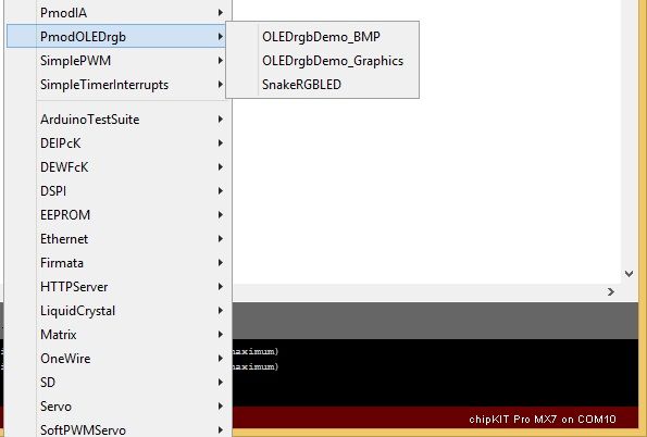
Once it is copied, restart MPIDE and click the Open button. You should see OLEDrgb in the drop down menu as depicted below.
This PmodOLEDrgb library contains several useful functions that make interfacing with the PmodOLEDrgb much simpler. It takes care of all of the timing and individual SPI transmissions that happen between your board and the Pmod.
Connecting the Hardware
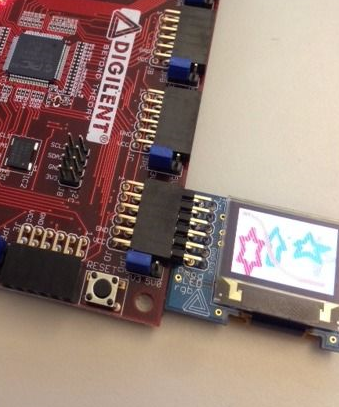
This is what tripped me up at first. What’s important to know is that the PmodOLEDrgb library uses the DSPI0 object class, which is not part of the standard SPI library, but rather part of the Digilent SPI library (DSPI). What this functionally means is that when using the PmodOLEDrgb library, the PmodOLEDrgb must be plugged into an SPI port that is accessed by DSPI0. On the chipKIT Pro MX3, this is found on Pmod port JE, as seen in the image below. If you are using a different chipKIT board, please refer to table 1 for a useful breakdown of which SPI ports are accessible by DSPI0 on each board. Note that there are two for which the PmodOLEDrgb library will not work without further tweaking of the code.
| chipKIT board | DSPI0 | SPI port | RM section | Has Pmod Ports | Pmod Shield Compatible |
| Max 32 | SPI2A | J13 | 3.5 Peripheral I/O Functions | No | No |
| Uc32 | Not supported | n/a | 3.5 Peripheral I/O Functions | No | Yes |
| MX3 | Not supported | n/a | 7 Serial Peripheral Interface (SPI) | Yes | No |
| Pro MX4 | SPI2 | JB | 10 Serial Peripheral Interface (SPI) | Yes | No |
| WiFire | SPI2 | J7 | 10.3 SPI | No | No |
| WF32 | SPI2 | J10 | 10.2 SPI | No | Yes |
| Pro MX7 | SPI1 | JD | 10 Serial Peripheral Interface (SPI) | Yes | No |
Table 1 showing which ports on which chipKIT boards will function smoothly with the PmodOLEDrgb library as well as a breakdown of which boards have Pmod host ports and which will work with the chipKIT Pmod shield.
Drawing Shapes on the Display
Open MPIDE (if it isn’t already) and create a new sketch by clicking Open, scrolling down to 1.Basics, and opening the BareMinimum project.
Go to File and click Save As. Name and save it. Next we need to include the necessary libraries. Add the following lines to the beginning of your program:
#include <DSPI.h>
#include <OLEDrgb.h>
Oledrgb OLEDrgb;
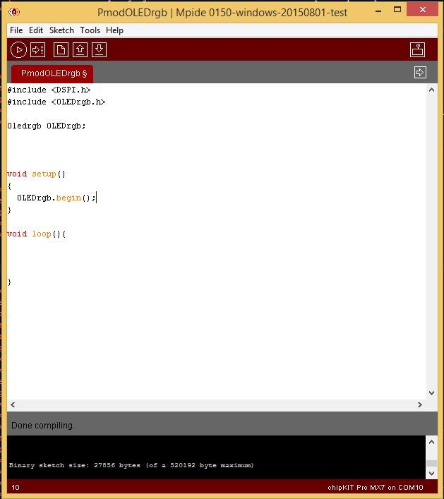
This will include the SPI and the OLEDrgb libraries, and will instantiate an Oledrgb object named OLEDrgb. Inside the setup() function, add the following line:
OLEDrgb.begin();
This function goes through the powering on sequence and configuration that the PmodOLEDrgb must go through to operate correctly. It should look like the image below .
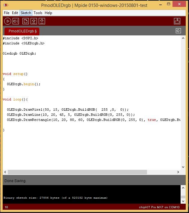
You can find several functions within the OLEDrgb.c file included in the library. These functions include DrawPixel, DrawLine, DrawRectangle, and DrawBitmap. There is also a helper function called BuildRGB (red,green,blue), this formats the RGB color into 2 bytes that can be read by the PmodOLEDrgb.
Calling OLEDrgb.DrawPixel(50, 15, OLEDrgb.BuildRGB(255, 0, 0)) will draw a pixel at coordinate (50,15) colored red.
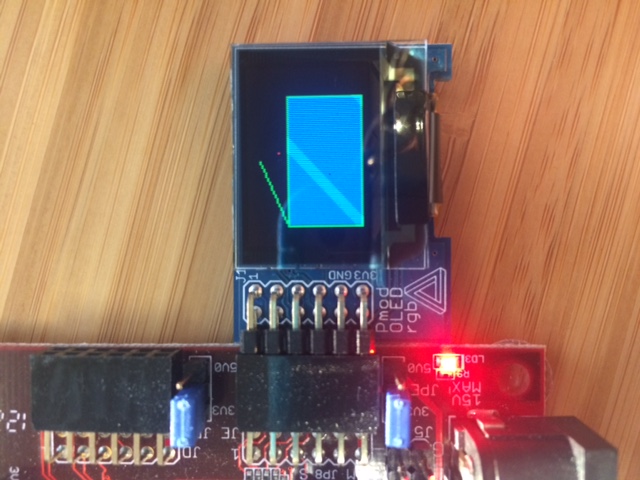
Calling OLEDrgb.DrawLine(10, 20, 45, 5, OLEDrgb.BuildRGB(0, 255, 0)) will draw a line from (10,20) to (45, 5) colored green.
Calling OLEDrgb.DrawRectangle(10, 20, 80, 60, OLEDrgb.BuildRGB(0, 255, 0), true, OLEDrgb.BuildRGB(0,0,255)) will draw a green rectangle from (10,20) to (80,60). True signifies that it will be filled in, and the last parameter sets that the fill will be blue.
Plug your chipKIT board into your computer via USB and select it in MPIDE by clicking Tools>Board>chipKIT>chipKIT MX3 (or other chipKIT board). Select the serial port that your board is plugged into by clicking Tools>Serial Port>COM___. In order to know which serial port to select, check the device manager on your PC for which port is dedicated to the USB interface. Once you are all set up, click the Upload button to upload it to your board! You should see some combination of the image below depending on whether or not you included all three example functions.
Hopefully this was useful in getting started with the PmodOLEDrgb and chipKIT PIC32 products. For more information, as well as instructions on how to display a bitmap, see our Instructable on Programming the PmodOLEDrgb on the ChipKIT Pro MX7. For more information on any of the products used here, please visit our Wiki.
And don’t forget to check out our Pmod Summer Sale for a great price on the PmodOLEDrgb!