

This post describes a senior design project that students at North Carolina State University (NCSU) worked on, in which the Analog Discovery 2 (AD2) is equipped with extra features tailored to its typical applications within NCSU’s senior design lab.
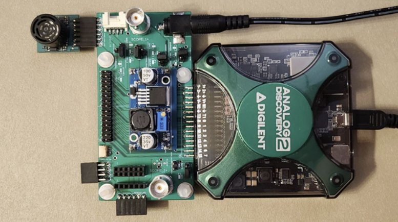
Because of the ever increasing popularity of the bring-your-own-device (BYOD) trend, students tend to bring their own laptops and AD2s to the lab. Thus, the goal of this project was to create an add-on module that allows the students to equip their personally-owned devices with the features of lab-owned equipment, allowing them to set up a test bench environment capable of expediting the prototyping process from the comfort of their own devices. The add-on board would allow students to skip the low-level development surrounding a sensor’s implementation and instead evaluate its function straight away to see if it fits their needs, potentially cutting out weeks of R&D. Once a sensor is chosen, the students can focus on their own product, knowing that they have chosen a device that delivers useful data.
To deliver the best possible product, a survey was sent out to students and faculty of the ECE department at NCSU. It allowed them to report features they felt were missing from a standalone AD2, among which the top responses were collected and formed into the basis for this project. The key features are: increasing available power, monitoring current, adding 8 additional analog inputs, providing common connectors, and making available a library of WaveForms scripts for common sensors. Additionally, the board was designed physically to be small enough to remain attached to the AD2 within its original case.
Available Power Increase
The AD2 sources its power from either the USB port it uses to communicate to a host computer, for a total of 0.5 W per channel, or a wall adapter connected via barrel jack, for a total of 2.1 W per channel. The total current output is 700 mA either way and is backed up by overcurrent and overvoltage protection circuitry to prevent damage to the internals of the AD2.
Any higher level of power must be sourced externally, so the expansion board includes an LM2569 buck converter. Its input range is 3 V to 40 V, with an adjustable output between 1.5 V and 1.5 V less than the input. It is rated for a maximum current of 3 A. With it, higher power devices such as servos, LED strips, or displays can be tested through the WaveForms software.
Current Monitoring
The AD2 can only measure voltages of ±50 V via its two scope channels. In order to support current and power monitoring, a shunt resistor/current sense amplifier (INA190A1IDCKR) and a hall effect sensor (TMCS1108A4UQDR) are included in the expansion board. The shunt resistor/current sense amplifier is intended to measure currents up to 1.32 mA with a sensitivity of 128 nA while the hall effect measures up to 10.75 A with a sensitivity of 0.8 mA.
Additional Analog Inputs
The AD2’s scope has two differential probe channels operating at up to 100 MS/s with a 14-bit range. To increase the number of analog inputs, the expansion board contains two 12-bit ADCs (ADS1015IRUGR), usable as four differential probe channels or eight single-ended probe channels. The chips communicate via I²C and operate between 128 S/s and 3.3 kS/s.
Common Connectors
The AD2 uses a 30 pin standard header to provide access to its power, analog, and digital features. To expand upon this 30-pin connection and to increase the ease of communication between common sensors and the AD2, various connectors are placed around the expansion board. These are two BNCs, one Grove connector, one Qwiic connector, and 5 Pmod headers, shown in the expansion board’s function diagram below.
Waveforms Scripting Libraries
Using WaveForms workspaces, “presets” for various sensors, mainly Pmods, were created and made available to the user. A global readme provides instructions on downloading and setting up a workspace, with sensor-specific details explained within the workspace. In this way, a student can set up and use a sensor with ease, allowing the student to focus on the sensor’s data output and evaluate its usefulness.
Further Reading
If you would like to have a more detailed look into the project, please visit the user manual here.
Is there a link to some further information or details?
PMODs are not only used at NCSU
Thank you for your comment! You can find more information on the project here: https://files.digilent.com/resources/test-and-measurement/analog-discovery-2/analog-discovery-2-functionality-expansion-user-manual.pdf
Hi , It would be good idea to put a link to the place you can find the pcb / cct diag and the Waveforms Scripting Libraries , on githubb
Thank you for your comment! You can find more information on the project here: https://files.digilent.com/resources/test-and-measurement/analog-discovery-2/analog-discovery-2-functionality-expansion-user-manual.pdf
Hi,
I would be interested in the extension board. Is it available?
Sounds and looks like a really great expansion board.
Are the PCB files as well as the Waveform libraries available to the public?
I would like to take a closer look at the project, to review if it could assist me in my job as vocational trainer for electronics.
Thank you for your comment! You can find more information on the project here: https://files.digilent.com/resources/test-and-measurement/analog-discovery-2/analog-discovery-2-functionality-expansion-user-manual.pdf
Could you add the the expansion board’s function diagram and a link to the project or its GitHub repo?
Thank you!
Thank you for your comment! You can find more information on the project here: https://files.digilent.com/resources/test-and-measurement/analog-discovery-2/analog-discovery-2-functionality-expansion-user-manual.pdf
is this expansion board available to non-students
Nice project! By any chance will the board design files and BOM be made available?
Thank you for your comment! You can find more information on the project here: https://files.digilent.com/resources/test-and-measurement/analog-discovery-2/analog-discovery-2-functionality-expansion-user-manual.pdf
Thank you to the pointer to the great documentation on the board. The remaining missing link is design files for the PCB layout (or a link to an outfit selling fabricated PCBs – maybe with proceeds going to NCSU’s ECE program).
I also think it would be great for the document to credit the North Carolina State University and the students and faculty responsible for the project.
Looking through the BOM provided in the user manual, is there any information on how to get the PCB as there is no information on that in the manual?
Very cool . The ease with which the device accommodates extra boards is really awesome.