


Step-by-Step Guide to Building an Arch Linux-Based Project
This paper will provide a step-by-step guide to build from ground up a Genesys ZU development board-based hardware and software project that is capable of running Arch Linux operating system (in theory any embedded ARM64 compiled Linux operating system can be used following this guide). All generated files are included and can be downloaded at the end of this guide. The development environment used to generate the example project was Vivado 2021.1, under Ubuntu Linux 20.4 LTS. Instructions on how to install Vivado under Linux and what licensing options are available can be found here. of the hardware development can be done under Windows OS, however, the bootloader and Linux environment compilation requires a working Linux environment or the use of Windows Subsystem for Linux.
All attachments can be found at the links below:
- BOOT.BIN
- FSBL System.BIF
- XSA
- HW Project
- System XDC
- Patches
- Pre-Generated Files
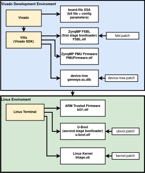
The project has two major parts: the hardware platform generated in the Vivado environment and the software platform, partially (FSB, device-tree) generated by the Vivado tool or the Vitis IDE. Other software components, namely, the ARM Trusted Firmware, u-boot bootloader and the Linux Kernel needs to be compiled separately in a Linux environment using an ARM64 compiler (the Xilinx development environment contains the necessary compiler).
Compiling the Hardware
- The first step is to create a new RTL project in Vivado. To use the Vivado executables and start the development environment from the terminal. The correct environment variables must be set by the settings64.sh script located in the Vivado installation folder. Every command during the implementation is executed in the terminal environment where the given source command was executed. Navigate to the installation directory <path to Xilinx folder>/Vivado/<vivado version>/ enter the following command:
$ source settings64.sh
- Afterwards, the Vivado environment can be started with the command:
$ vivado
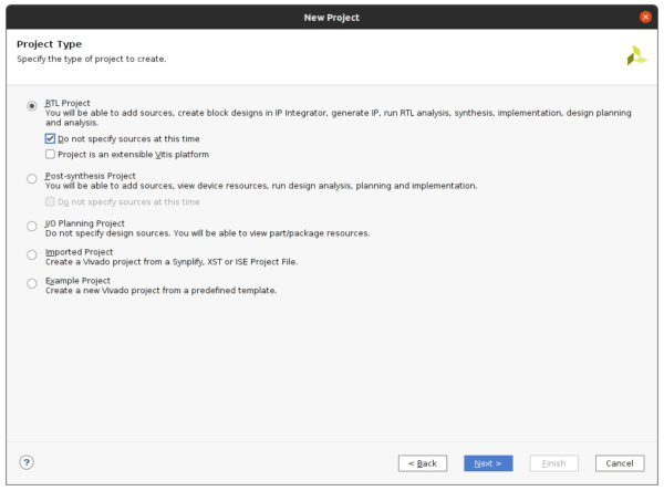
- After Vivado opens, select from the File menu -> Project, then New… to create a new Vivado project. Select RTL Project, then Next.
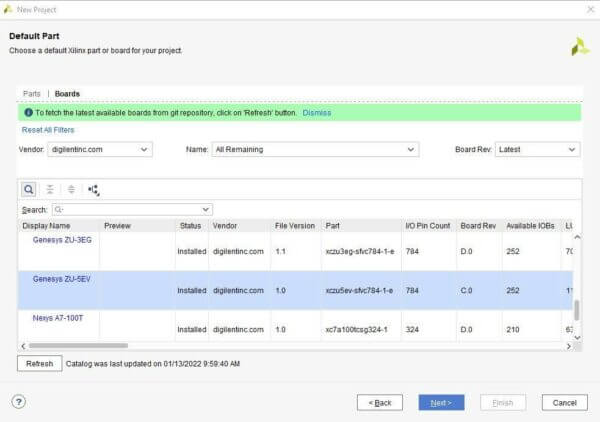
- At the configuration screen the correct board file must be selected in the Xilinx parts selector (Figure 3). At the time of writing this guide, Vivado 2021.1 and all the older Vivado versions do not contain the new Genesys ZU board specification files. The user has to download them from https://github.com/Digilent/vivado-boards, following the steps in Section 3 of the Installing Vivado, Xilinx SDK, and Digilent Board Files guide on the Digilent Wiki.If the files are correctly installed, the Genesys ZU boards will become selectable from the Xilinx parts selector window.
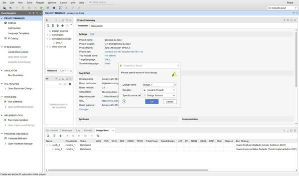
- After the project is initialized, a new Block Design can be created.
- At least the Zynq UltraScale+ MPSoC core has to be added to the project. Select the Run Block Automation at the top green line to configure the ZynqMPSoC core with the Digilent preset that is included in the board specification files.
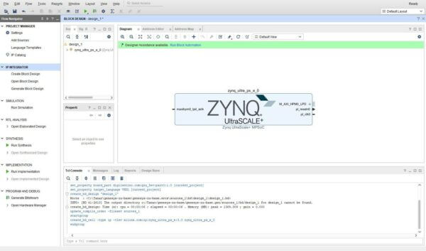
Figure 5 – Inserting the Zynq Core 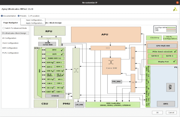
Figure 6 – the ZynqMP core configuration - When adding and configuring any additional modules, check the connections and the address allocation of the AXI Bus. The example project contains two AXI-GPIO modules connected to the four LEDs and the four switches on the board (if unused the AXI Slave HP0 should be disabled otherwise compilation errors can appear). Figure 7 shows the basic project with two GPIO modules connected, one to the switches and one to the LEDs on the board.
The emio_enet0_enet_tsu_timer_cnt ports can be left unconnected.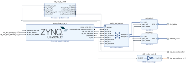
- The Display Port AUX signals can be connected by creating a new constraint file and adding appropriate ports (system.xdc, Figure 8).
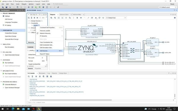
Figure 8 – Creating a new constraint file 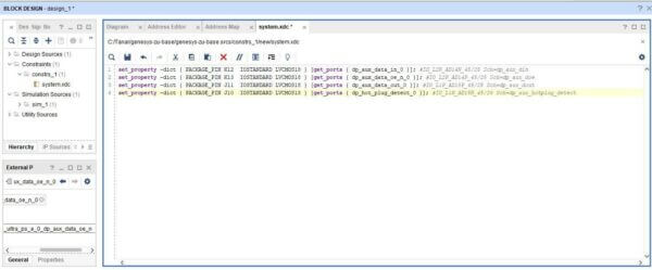
Figure 9 – Contents of the constraint file - After all user modules are connected and configured, the user must generate the HDL Wrapper for the block design presented in Figure 7. After this, the bitstream can be generated by clicking on the Generate Bitstream link from Flow Navigator panel. This will synthesize and implement the project.
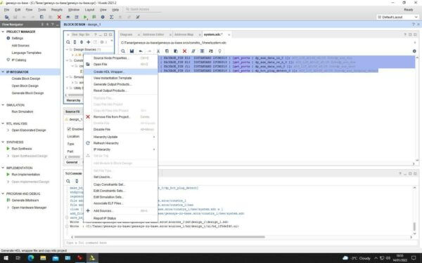
Figure 10 – Creating the HDL Wrapper
Compiling the Software
-
-
- We will generate and compile the necessary software components to run the Linux environment on top of the generated hardware components. The FSBL, PMU Firmware and the device-tree can be generated from Vivado tool or Vitis IDE, depending on the used development environment. The FSB will preconfigure the board, load the bitstream in the reconfigurable part of the chip and load the device-tree, boot loader and the kernel to memory. Afterwards, it executes the ARM Trusted Firmware. In Vivado 2021.1 the generate hardware project, can be exported to Vitis IDE (File->Export->Export Hardware). If the “Include bitstream” option is selected, this will create the platform file with XSA extension that will include all configuration files and the bitstream.
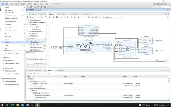
Figure 11 – Exporting the Design to Vivado/Vitis SDK - Afterwards, the Vitis IDE can be started by selecting the Launch Vitis IDE from the Tools menu or by executing the following command from the terminal:
$ vitis
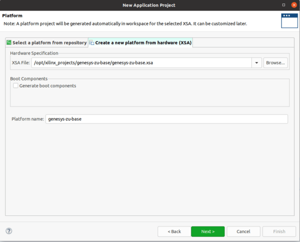
- In the Vitis IDE environment, after selecting the File->New->Application Project, the XSA file created in Vivado needs to be selected. Under the Create a new platform from hardware (XSA) tab, click on Browse and select the generated board file with the XSA extension.
- Generating the FSBL and PMU firmware is possible through 2 methods:
The first one, inside the hardware platform project, by ticking “Generate Boot Components”. The Digilent-provided FSBL is required and should be added to the Vitis workspace in the Xilinx->Software Repositories menu (Vitis -> Window -> Preferences -> Xilinx -> Software Repository).
Download the FSBL source code from https://github.com/Digilent/embeddedsw/tree/genesys-zu-21.1.
Add the path as a local software repository and Vitis will use the Genesys ZU-specific FSBL instead of the generic one. - The second one, by Deselecting “Generate boot components” (Figure 12) and using fsbl.patch file. We will be creating the FSBL manually. This method is used in this tutorial.
- Generating the FSBL and PMU firmware is possible through 2 methods:
- The next step is to create a new domain with the default values, on the Application Project Details window for the Application project name, type FSBL. The target processor is the psu_cortex53_0.
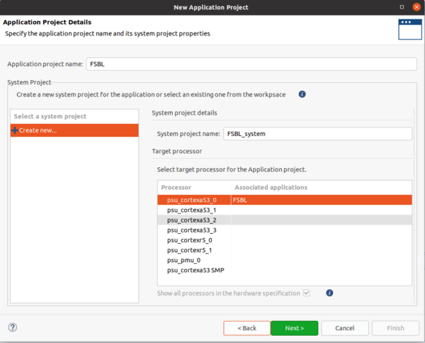
Figure 13 – Application Project Configuration Step 1 - Create new domain and keep the default values. On the next window select the Zynq MP FSBL template.

Figure 14 – Application Project Configuration Step 2 - The FSBL must be modified to initialize the Wifi module on the board. The spi_gpio.h and spi_gpio.c files will be added to the project and the xfsbl_board.h and xfsbl_board.c files are also modified with the attached patch file. The ZynqMP FSBL is located in the on-chip memory (OCM) at 0xFFFC0000 – 0xFFFE9FFF. After modification it might not fit. The xfsbl_config.h file can be modified to reduce the FSBL size, by removing unused modules. A more detailed description can be found on this link. The modifications can be integrated by applying the FSBL.patch in the src directory of the FSBL project. Navigate to the Vitis workspace directory, afterwards FSBL, then src, and copy the FSBL.patch inside this directory and execute:
$ patch -p0 < fsbl.patch
- After patching the source file the FSBL.elf image can be built.
- The PMU Firmware is responsible for some Power Management, Security, Functional Safety etc. functions that most users might not need to modify. However, in some cases, the execution of the FSBL might hang at “Protection configuration applied Running” dialogue, if the firmware is not present in the BIN file. The PMU can be generated by File->New->Application Project. Select the previously created platform. At the Application Project Details window, select the Show all processors in the hardware specification and create a new application on the psu_pmu_0 processor.
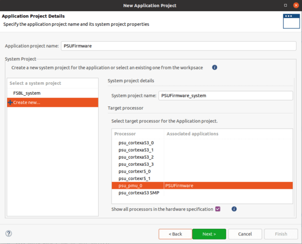
Figure 16 – PMU Firmware application project configuration Step 1 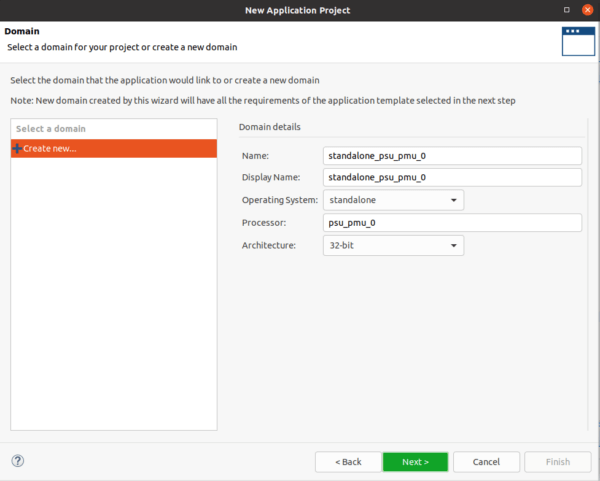
Figure 17 – PMU Firmware application project configuration Step 2 - Afterwards, select the “ZynqMP PMU Firmware” template to create the default PSU Firmware.
- To generate the device-tree automatically, the Xilinx Device–Tree generator repository must be downloaded with the following commands and added to the project repositories. The following commands are given in Linux Terminal environment inside the user’s home directory write access is needed on the directory to execute the following commands:
$ git clone https://github.com/Xilinx/device-tree-xlnx
$ cd device-tree-xlnx/
$ git checkout xlnx_rel_v2021.1 (use the version of the development environment)
- Afterwards, the device-tree can be generated from the Vitis environment. Add the repository to the Vitis workspace in the Xilinx->Software Repositories menu (Vitis -> Window -> Preferences -> Xilinx -> Software Repository). Generate the device-tree (Vitis -> Xilinx -> Generate Device Tree).
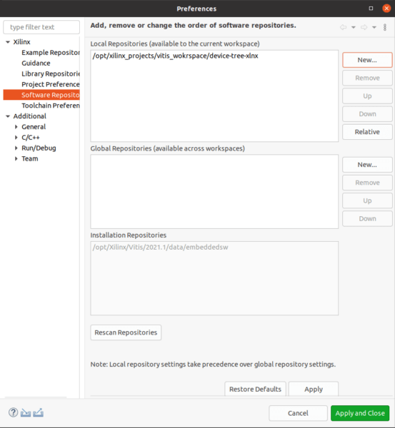
Figure 18 – Adding device tree repository 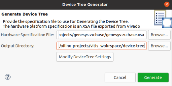
Figure 19 – Device tree GUI generation - The generated board files do not contain board specific blobs before compilation. The attached device-tree.patch must be applied to the folder where the files were generated. Navigate to the folder given at the Generate Device Tree prompt, copy the attached device-tree.patch file to this directory and execute the command:
$ patch –p0 < device-tree.patch
This will include the board-specific configuration.
- The following commands will create the binary formatted device-tree used by u-boot and the Linux kernel. The dtc command is part of the Vivado environment the command must run from a terminal where the settinsg64.sh was sourced.
$ gcc -I . -E -nostdinc -undef -D__DTS__ -x assembler-with-cpp -o system.dts system-top.dts
$ dtc -W no-unit_address_vs_reg -I dts -O dtb -o genesys-zu.dtb system.dts - The remaining modules are generated entirely from the Xilinx git repository under Linux. The ARM Trusted Firmware has to be generated. The FSBL will start the firmware that will start the u-boot boot loader. Run the commands from a terminal where the settinsg64.sh was sourced. Navigate to a folder with write permissions and execute:
$ git clone https://github.com/Xilinx/arm-trusted-firmware
$ cd arm-trusted-firmware/
$ git checkout xlnx_rebase_v2.4_2021.1
$ make CROSS_COMPILE=aarch64-none-elf- PLAT=zynqmp RESET_TO_BL31=1The generated binary bl31.elf file can be found at /build/zynqmp/release/bl31/
- Next is the u-boot bootloader generation. First, clone the second stage bootloader and set the u-boot environment. Navigate to a folder with write permissions and execute:
$ git clone https://github.com/Xilinx/u-boot-xlnx
$ cd u-boot-xlnx/
$ git checkout xilinx-v2021.1
- Before u-boot compilation, some device specific configuration must be done, by copying the previously generated device-tree blob into the project:
$ cp <path to generated device-tree>/genesys-zu.dtb <path to u-boot-xlnx>/arch/arm/dts/
- Set the environmental variables. If the environment is set up correctly, the Xilinx provided compiler can be used.
$ export CROSS_COMPILE=aarch64-linux-gnu-
$ export ARCH=aarch64
- Generate a base configuration file for default ZynqMP configuration. This will be modified by the attached patch file.
$ make xilinx_zynqmp_virt_defconfig
- Copy the provided uboot.patch file in the u-boot-xlnx directory and run the following command to configure u-boot:
$ patch -p0 < uboot.patch
- Now compile u-boot with the make command.The u-boot.elf file can be found at the source directory u-boot-xlnx if the compilation was successful.
- The last component is the Linux Kernel. First, some additional packages have to be installed on the Ubuntu system with the following command:
$ sudo apt-get install libncurses-dev gawk flex bison openssl libssl-dev libelf-dev libudev-dev libpci-dev libiberty-dev autoconf
Afterwards, clone the Xilinx maintained kernel from their git repository. Run the commands from a terminal where Navigate to a folder with write permissions and execute:
$ git clone https://github.com/Xilinx/linux-xlnx
$ cd linux-xlnx/
$ git checkout xilinx-v2021.1
Make a ZynqMP based default configuration
$ make ARCH=arm64 xilinx_zynqmp_defconfig
Copy the provided patch file to the linux-xlnx folder and apply it.
$ patch -p0 < kernel.patch
Add any additional configuration or drivers by running the menuconfig command. When done, the kernel can be compiled.
$ make ARCH=arm64 menuconfig
$ make ARCH=arm64
The compiled kernel image can be found at <path to linux-xlnx>/arch/arm64/boot. The name of the binary kernel file is Image, without extension. If the graphical interface is used to generate the BOOT.BIN file, the kernel file must have extension. It can be renamed Image.ub.
- All the necessary files are generated to run the Linux the kernel. The kernel can run a small user environment from a compressed image that is extracted to the memory. This ramdisk image contains the init script that will chroot into the Arch Linux environment. The image is attached, and it contains a minimal BusyBox environment and the init script (uramdisk.image.gz).Afterwards, all files must be stitched together to generate the device boot image, the BOOT.BIN file. This is the file that the baked-in firmware will search for on the FAT32 formatted first partition of the SD card. The file can be generated from terminal, using the attached bif file. All the files in the bif file are invoked without a path. This means that all generated files must be in the same folder as the bif file. Generate the boot image with the following command:
$ bootgen -arch zynqmp -image FSBL_system.bif -o BOOT.BIN –w
The BOOT.BIN can also be generated from the graphical environment, as the user can import the provided bif file or create a new one.
When creating a new bif file, the first file it has to contain is the FSBL bootloader and which processor it will run on, designated by the destination_cpu option.
[bootloader, destination_cpu = a53-0]FSBL.elf
The second position is the PMU firmware if it exists.
[pmufw_image]PMUFirmware.elfThen the user can specify with the destination_device=pl option, the bit file for the reconfigurable part of the FPGA and the FSBL will configure it.
[destination_device = pl]genesys-zu.bitThe Zynq Ultrascale devices use the ARM Trusted Firmware secure software stack, where the Linux operating system is running. As the OS runs at ARM EL1/0 level, it has limited access to system or security-critical registers and devices. All calls from Linux to those registers and devices are routed trough the ARM Trusted Firmware, which is running at EL3, this is the next file that the FSBL loads with the EL3 level set.
[destination_cpu = a53-0, execution_level = el-3, trustzone]bl31.elfThe last file needed is the u-boot bootloader that will load the Linux operating system. This will run at trust level EL2.
[destination_cpu = a53-0, execution_level = el-2]u-boot.elfU-Boot has the capability to load the Linux kernel, the ramdisk and the device-tree from multiple external sources. In the given example project these files are stitched in the BOOT.bin file with a load option telling the FSBL to load the corresponding file to the given memory address. This way, U-Boot doesn’t have to load any images just simply boots by directly issuing a matching booti command.
[load = 0x2a00000, destination_cpu = a53-0]genesis-zu.dtb [load = 0x2000000, destination_cpu = a53-0]uramdisk.image.gz [load = 0x3000000, destination_cpu = a53-0]Image.ub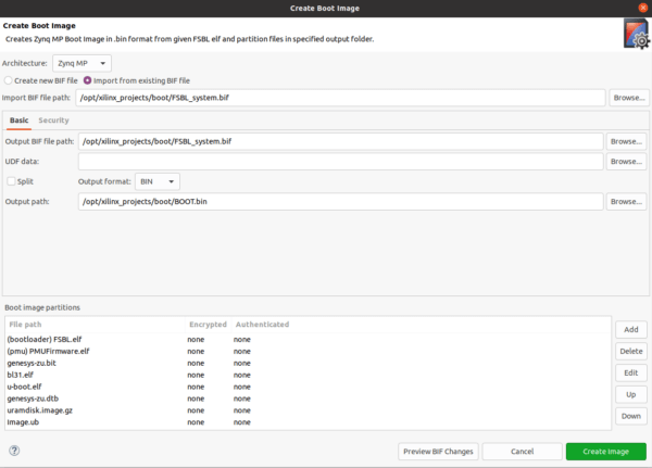
Figure 20 – Creating the Boot Image from the GUI When the BOOT.BIN is generated, it must be copied on the FAT32 formatted first partition of an SD card, and the second partition must be ext4 formatted, containing the extracted ARCH Linux files downloaded from this link. Extract the archive using the tar command to the second partition of the SD card.
$ tar -xvf archlinuxarm-aarch64-latest.tar.gz
The SD card can be formatted from any Linux Distribution using a GUI app like gparted or from terminal, using the fdisk command. If everything is applied correctly, the Arch Linux operating system will start, if the JP3 jumper is set to the SD card position. Connect the USB cable to the J8 port, open a serial terminal app like Putty, select the virtual COM port, set baud rate to 115200. If everything is set correctly, the Arch Linux will boot and a login terminal will appear.
- We will generate and compile the necessary software components to run the Linux environment on top of the generated hardware components. The FSBL, PMU Firmware and the device-tree can be generated from Vivado tool or Vitis IDE, depending on the used development environment. The FSB will preconfigure the board, load the bitstream in the reconfigurable part of the chip and load the device-tree, boot loader and the kernel to memory. Afterwards, it executes the ARM Trusted Firmware. In Vivado 2021.1 the generate hardware project, can be exported to Vitis IDE (File->Export->Export Hardware). If the “Include bitstream” option is selected, this will create the platform file with XSA extension that will include all configuration files and the bitstream.
-
Where is fsbl.patch file to download?
In fact.. where are all the files that are referred by the article, such as uboot.patch?
I’ve added them all to the top of the post! Thanks for pointing out my error!