

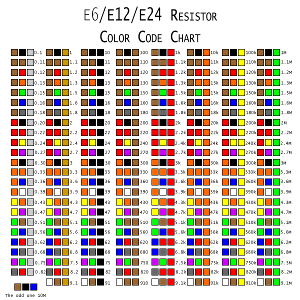
If you’ve been around electronics for a while, you’ve probably noticed that components like resistors, capacitors, zener diodes, and inductors come in some odd values. Looking at the chart below, there seems to be no clear rationale behind the values, but there is a pattern. 47kΩ resistors and 22μF capacitors are everywhere, but not 40kΩ or 50kΩ resistors, or 20μF or 30μF capacitors. So what’s the deal? It all has to do with preferred numbers.
We have to go back a few years to 1877 France. The French military used balloons for various purposes and of various sizes, and they had to be anchored using cables. Over time, they ended up with 425 different sizes of mooring cables that had to be individually ordered and inventoried. Talk about a nightmare.
Enter Charles Renard. He was tasked with improving the balloons, but discovered this rat’s nest of cables in the inventory closet instead. He spent some time thinking about it and came up with a series of 17 cable sizes that would allow for every type of balloon to be properly moored. Each size of cable had a max/min rating that just overlapped it’s neighbor above and below, so every required value was covered by one or more cable. This system of numbers became known as the “Renard numbers” and was later included in the “preferred numbers” when the concept was expanded for other applications and became an international standard with ISO (International Organization for Standards) 3 in 1952.
Since then, numerous international standards have been adopted by ISO for countless things, but one of those is how we identify certain electronic components. Using the same idea that Renard developed, these components are labeled with what are known as E-series values within the preferred number system. The lowest value is E6, which enumerates six values between two consecutive powers of 10, i.e., between 10 and 100 or between 10k and 100k. Starting with 10, we increase that value by roughly half and we get 15. Increase by roughly half again and we get 22. Continuing this trend, rounding as needed, and we end up with the series 10, 15, 22, 33, 47, and 68. Components built to the E6 standard have a 20% relative error tolerance, and if we look at the values again we’ll see a trend. Starting with 10 again and adding 20% error we end up with 12. Moving to 15 and subtracting 20% we get… wait for it… 12. Moving up from 15 we get 15 + 20% = 18 and 22 – 20% = 17.6. This trend repeats no matter what range of powers of 10 you use, as long as they are consecutive. So 47kΩ + 20% = 56400, while 68kΩ – 20% = 54400.
Look again at the values 47 and 68. The max/min values overlap right about 56, don’t they? That sounds familiar. The E12 standard uses all of the same values as E6, but with 6 more values mixed in. These 6 additional values are roughly where the E6 values overlap, and now in order to cover the entire range our %-error is reduced to 10%. Starting again at 10, we have 10, 12, 15, 18, 22, 27, 33, 39, 47, 56, 68, and 82. The math holds true here as well, with the error values just slightly overlapping.
There are four more E-series as well, namely E24, E48, E96, and E192. The image above lists all values included in the E6/E12/E24 standards. With each doubling of values between consecutive powers of 10, there is an associated halving of the %-error allowance as well. So E24 values have a +/- %-error of 5%, E48 is set at 2%, and so on. The values associated with E192 are also available with 0.25% and 0.1% tolerances, and E24 and E96 are also available with 1% tolerances.
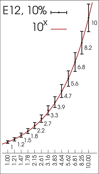
Below is a simple graphical view of how the E12 values relate to one another. Along the bottom of the graph you will see the first 13 terms of an ideal geometric sequence as well. (The sequence is given by y=10^(i/b), where b is the value of the series (e.g. 12) and i is the term desired (e.g. the 8th term would yield 10^(8/12)=4.64).) Notice how closely the values are related.
While it is possible to have a 3.3kΩ resistor with 20% tolerance test out between 2.64kΩ and 3.96kΩ, I would be hesitant to use it. I want 3.3kΩ, so I tend to use resistors with a higher tolerance, usually 5%, so I can just reach in my bin and know that I’m reasonably close. Looking back at the table in the beginning, we see that there are values of 68 and 75 listed. If I’m looking for a value of 70 (or some multiple power of 10, like 700), what can I do to achieve it? I can certainly start testing every 68 valued resistor I can find (75 is just out of range of 5% tolerance), hoping to find one that is just right, but just because it says 5%, doesn’t mean it is. That is a maximum allowance, and my experience has been that the tolerances are much tighter than that. I could go up to an E96 (681 0r 715) or even E192 (698!), but resistors with that level of %-error tolerance are not common and cost more. I just want something simple that I already have in my bin! The answer is actually quite simple. Just add a 33 and a 47 and call it good. You get your 70 +/- whatever tolerance you want since 33 and 47 are preferred numbers in every E-series. The point is that any value can be made for any circuit requirement simply by adding components together. When you throw in the rules for calculating components in series and parallel, the combinations are endless.
Good job! I really enjoyed reading this post.
Fantastic work, It is very informative post. Thanks for sharing.
33+47 equals 80
Wow, thanks!
Sorry but I could not help myself! There is a slight error in your article. “Just add a 33 and a 47 and call it good. You get your 70 +/- whatever tolerance you want since 33 and 47 are preferred numbers in every E-series.” Adding 33 and 47 gives you 80, not 70. Using a 22 and 47 will give you 69, which given the tolerance, will normally be close enough.
Otherwise, well written article, clear and to the point.
It makes sense now.
phi
Should not be the values separated based on logarithmic scale (base 10^(1/10) ) so:
1.0
1.2589254117941673
1.5848931924611136
1.99526231496888
2.5118864315095806
3.1622776601683804
3.981071705534974
5.011872336272725
6.309573444801935
7.943282347242819
10.00000000000000
?