

Fritzing is a software tool that allows you to create circuit images to facilitate the easy replication of projects and labs for students or hobbyists.
It enables you to create Fritzing images of your complicated circuits by dragging and dropping components.
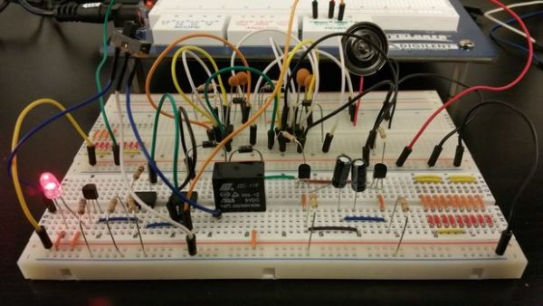
This helps avoid messy pictures of circuits where you can’t really see any of the connections. We’ve been working on creating additional parts such as the Pmods and microcontroller boards, to expand the types of circuits that can be represented.
However, representing the Analog Discovery 2’s oscilloscope, waveform generator and power supplies in a Fritzing image was challenging. That is, until now!
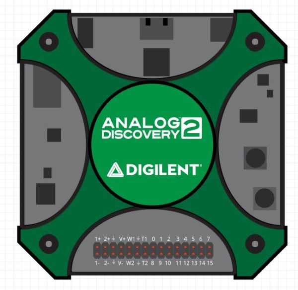
There is now a Fritzing part for the Analog Discovery 2. This allows you to create easy to follow tutorials and labs that describe the circuit, and use its inputs and outputs. The 30 pin connector that provides access to the 100MSPS speed of the Analog Discovery 2 has been moved to the top of the device to accommodate for 2D images.
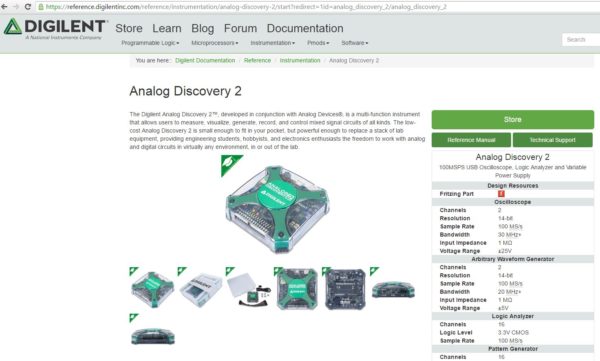
You can download the Fritzing part from the Analog Discovery 2 resource center page. Once downloaded it can be imported into Fritzing, and then used in all of your projects or curriculum.
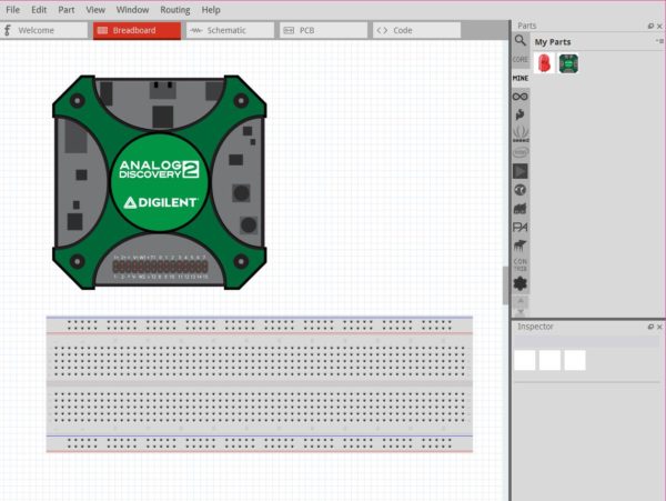
To use it, you drag the Analog Discovery 2 from the “my parts bin” and onto your breadboard image. You are now ready to wire up whatever circuit you need to represent.
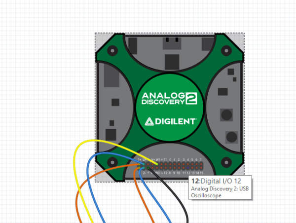
Each of the pins on the 30 pin connector is labeled corresponding to the pin out diagram. This way you can hover over the pin to see what tool you can access from it. For example pin 12 is one of the Digital I/O pins.
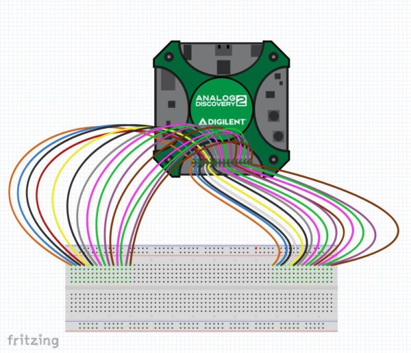
Although the flywires aren’t on the Fritzing part, Fritzing itself contains wires in all the colors that you need. When connecting to the waveform generator you can use yellow wires, when connecting to ground you can use black, and so on.
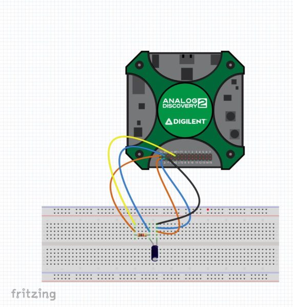
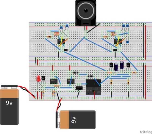
To create an image of your circuit, you can drag the components from the various parts bins onto the breadboard and then connect the wires to the Analog Discovery accordingly.
This gives a clear image of the circuit you built. Now students can easily replicate the circuit they are required to build without the need for an additional wiring video or the time spent trying to take an picture of it. They can get to straight to the stage of discovery, bypassing confusion about where components are supposed to connect. You can demonstrate the tools they need to use including oscilloscopes, triggers, waveform generators, data loggers, power supplies, network analyzers, spectrum analyzers, logic analyzers, pattern generators, and static I/O.
Download the Analog Discovery 2 Fritzing part from the Resource center and start making easy to replicate circuit images with the Analog Discovery 2. We’d love to see what you come up with!